32
Subject to modication
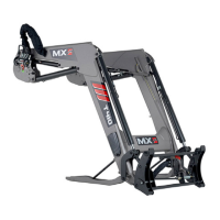
— Ensure that the male and female couplings are clean before
connection. Clean them if necessary.
— Connect the hoses for implements with hydraulic functions.
■
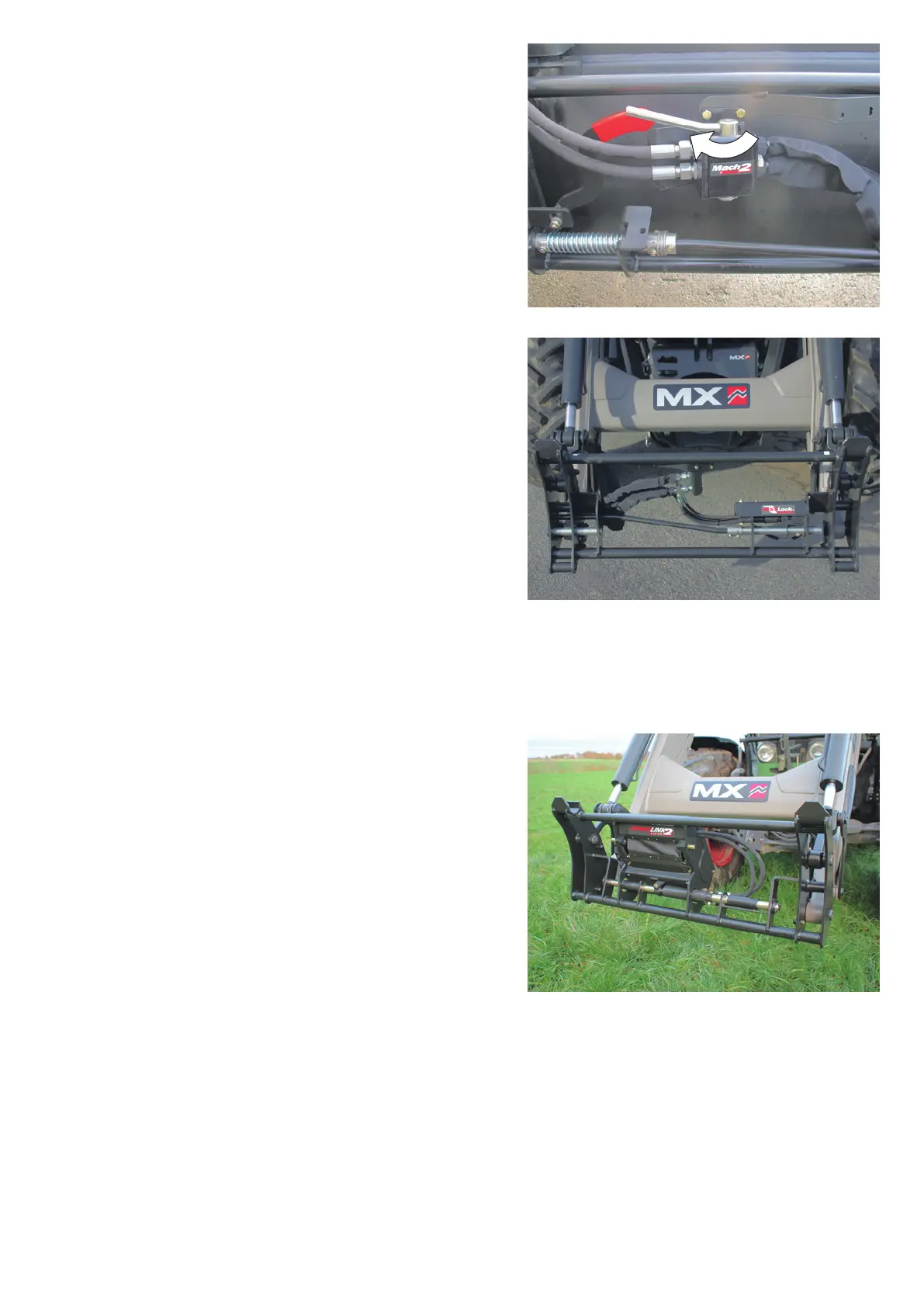
9.2 FAST-LOCK implement carrier
— “Open” position, to allow space for the implement parts.
— Align the loader with the implement,
— Fit the implement carrier onto the implement,
— Crowd slightly and raise the loader to lift the implement from the
ground.
— Press the green and padlock buttons while moving the dumping
lever to the left (crowding).
— The implement is now locked.
NOTE: If the implement has one or more hydraulic functions,
connect the hoses.
■
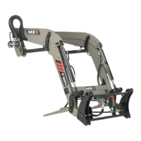
9.3 SPEED-LINK 2 implement carrier
— Before attaching an implement, make sure that the locks are in
"open" position. The locking indicator located at the rear of the
SPEED-LINK 2 frame is red.
— Align the loader with the implement, t the implement carrier
onto the implement, crowd slightly and lift the loader to raise the
implement from the ground.
— Press the green and padlock buttons while moving the dumping
lever to the left (crowding). The implement is now locked.
— The locking indicator is green.
NOTE: It is possible to use an implement with a maximum of one
DA function but not tted with the SPEED-LINK 2 connection. If
necessary, connect the two couplings on the rear SPEED-LINK
2 frame housing after depressurizing the 3rd function hydraulic
circuit.
■