1 GND 14 GND
2 ssAI8+ 15 ssAI8–
3 ssAI9+ 16 ssAI9–
4 GND 17 GND
5 ssAI10+ 18 ssAI10–
6 ssAI11+ 19 ssAI11–
7 GND 20 GND
8 ssAI12+ 21 ssAI12–
9 ssAI13+ 22 ssAI13–
10 GND 23 GND
11 ssAI14+ 24 ssAI14–
12 ssAI15+ 25 ssAI15–
13 GND 26 GND
Connecting Voltage Sources to Simultaneous Analog Input
All sixteen inputs share a common ground that is the same as the digital and analog ground of
the GPIC. The differential input signal and absolute voltage of each input should be within the
input range of each channel. Refer to the sbRIO-9687 Specifications for details.
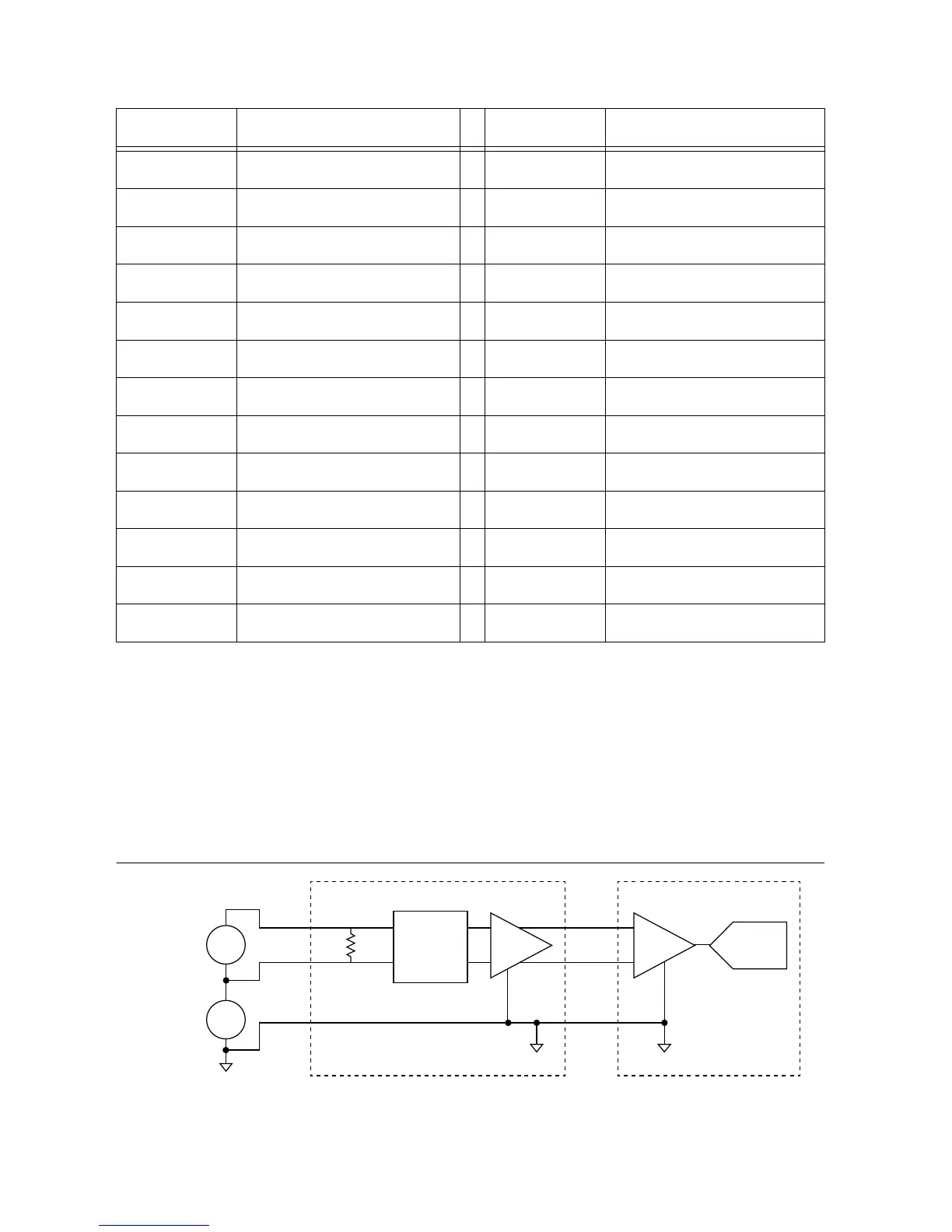
The simultaneous sampling analog inputs are differential, so the input measures the voltage
between the positive and negative terminals.
Figure 7. Connecting a Differential Voltage Signal to Simultaneous AI

 Loading...


