Table 15. Simultaneous Sampled Analog Input Signal Source Selection (Continued)
Input 1 (Inverters) Input 2 (AI Connector)
GPIC Input Name Switch Contact Pair Name Switch Contact Pair
AI9± U DC 2 SW35 3, 4 ssAI9± SW35 1, 2
AI10± U DC 3 SW37 3, 4 ssAI10± SW37 1, 2
AI11± U DC 4 SW43 3, 4 ssAI11± SW43 1, 2
AI12± U DC 5 SW39 3, 4 ssAI12± SW39 1, 2
AI13± U DC 6 SW24 3, 4 ssAI13± SW24 1, 2
AI14± — — — ssAI14± connected —
AI15± — — — ssAI15± connected —
Notice Only one signal source should be connected to each GPIC analog input at
one time. Connecting two signal sources in parallel can produce unexpected results.
Analog inputs from inverters are shared between the half-bridge modules and the full-bridge
modules. For proper operation, each analog line should be driven by only one inverter. Refer
to Inverter Signals on page 9 for more information.
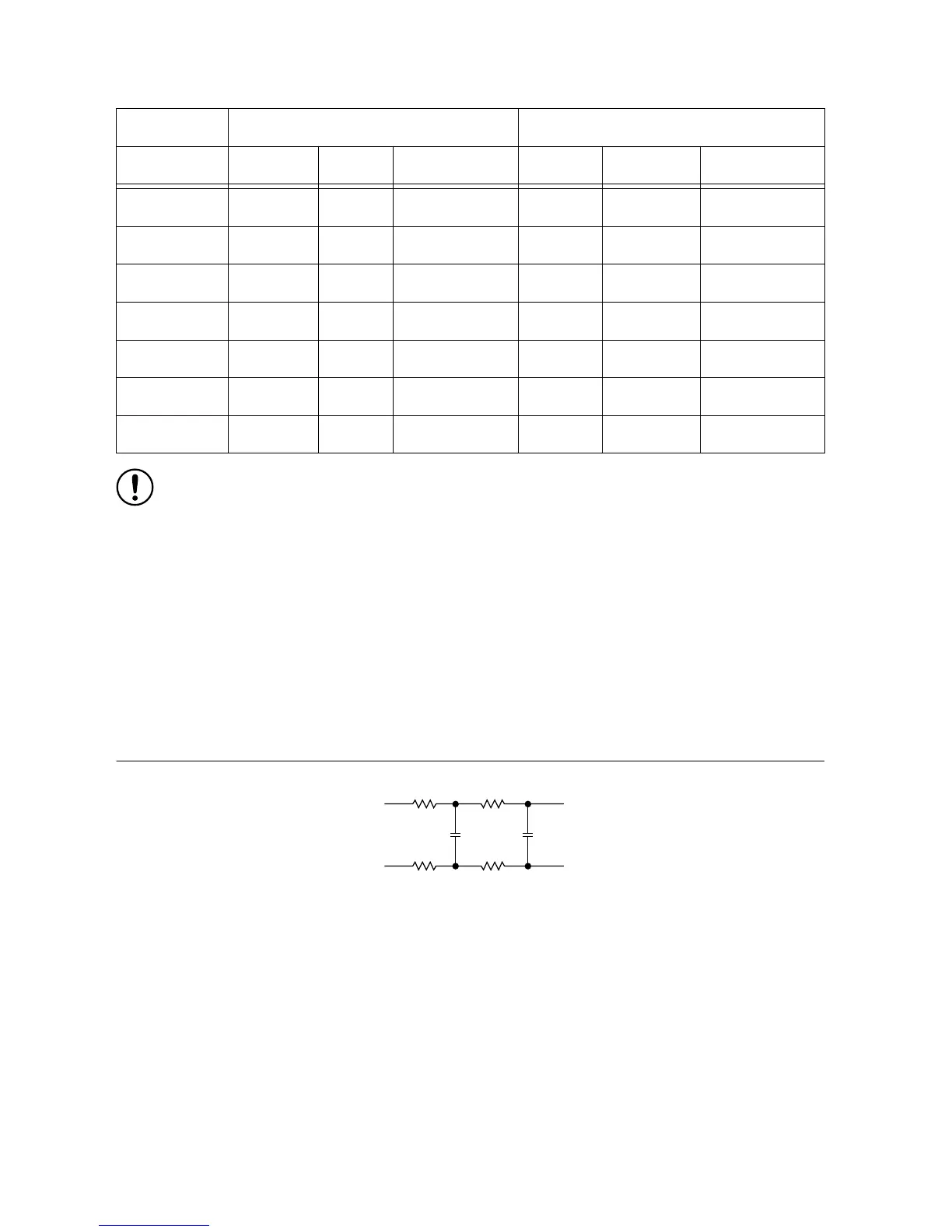
Low Pass Filters
The sbRIO-9687 provides a low pass filter for each analog input. The filter has two stages that
are populated by default with 10 kΩ resistors and 3.3 nF capacitors. Refer to the sbRIO-9687
Specifications for details about the filter characteristics.
Figure 10. Simultaneous Sampled AI Input Low Pass Filter
The first two filter resistors (R1) have a second functionality on the board and have a value of
10 kΩ. Other filter elements can be changed to set filter characteristics as required by the
application. The R2 has a default value of 10 kΩ (0603 footprint), and C1 and C2 have a
default value of 3.3 nF (0805 footprint).
sbRIO-9687 User Manual | © National Instruments | 21

 Loading...


