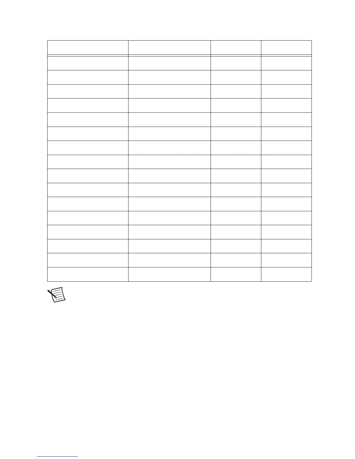
AI0± R195, R207 C122 C121
AI1± R219, R227 C142 C141
AI2± R219, R226 C140 C139
AI3± R194, R206 C120 C119
AI4± R183, R170 C105 C104
AI5± R138, R153 C88 C87
AI6± R169, R182 C103 C102
AI7± R137, R152 C86 C85
AI8± R68, R75 C47 C46
AI9± R107, R118 C70 C69
AI10± R99, R116 C66 C65
AI11± R80, R66 C50 C49
AI12± R38, R50 C31 C30
AI13± R12, R24 C14 C13
AI14± R49, R37 C29 C28
AI15± R23, R11 C12 C11
Note For a different cut-off frequency, change only the filter capacitors while
keeping C1 and C2 of equal value.
Gain Stage
Each analog input channel has a gain stage immediately after the low pass filter. Gain can be
set as x1, x2, x3, and x4. The output of the gain stage will work correctly only if the input
voltage at the simultaneous AI connector is within the common mode and differential range
listed in the sbRIO-9687 Specifications for each selected gain.
The gain should be set to use as much of the GPIC input range as possible. When current
signals are converted to voltage with onboard current-sensing resistors, it is preferable to set
the gain to the maximum value so that power dissipation from resistors is minimized.
Refer to the following tables for information regarding simultaneous sampled AI gain
configuration and related DIP switch reference designators and contact assignments.
22 | ni.com | sbRIO-9687 User Manual

 Loading...


