Performance Verification
22
• Signal/Function Generator, able to deliver 0 to ±5
volts peak-to-peak at 1,000 Hz, 100 mA
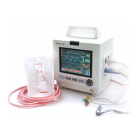
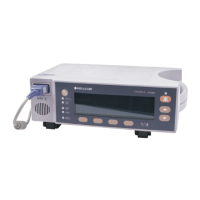
• Pulse oximeter or monitor
• ECG monitor (RA, LA, LL)
LED Current to Photodetector Current Test
Note: The initial setting on the Signal Generator is 1000
Hz, Square wave, 0 to 5 volts peak-to-peak. The
RED and IR LEDs will be tested separately.
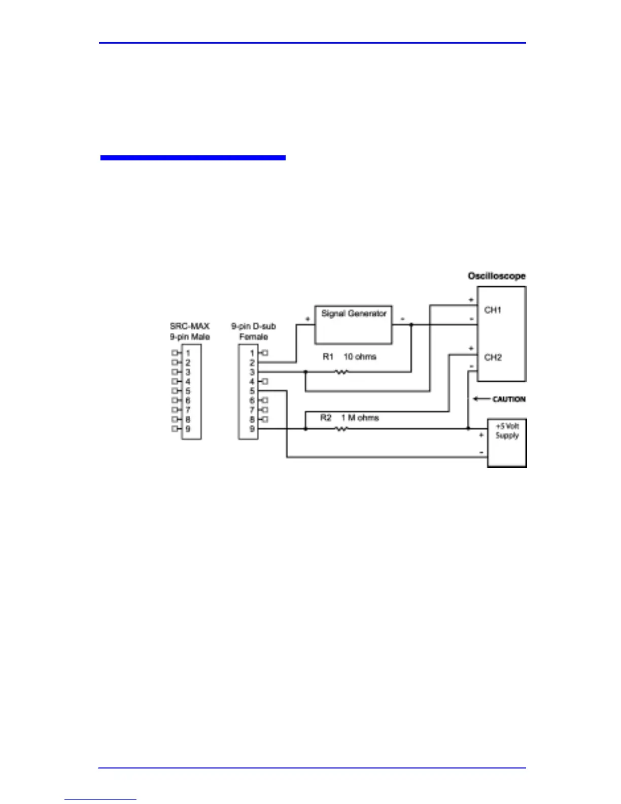
Figure 11: Block Diagram
1. Connect a 10 ohm resistor (R1 in Figure 11) to pin 3 of a
9-pin D-sub female connector. The other side of the 10
ohm resistor should be connected to the Signal
Generator’s ground. See Figure 11.
2. Connect the positive side of the Signal generator to pin 2
of the 9 pin D-sub female connector.
3. Connect the oscilloscope channel 1 (+) to the junction of
pin 3 and the 10 ohm resistor.
4. Connect the oscilloscope channel 1 (-) to the junction of
the Signal Generator’s ground and the 10 ohm resistor.