Performance Verification
SRC-MAX 25
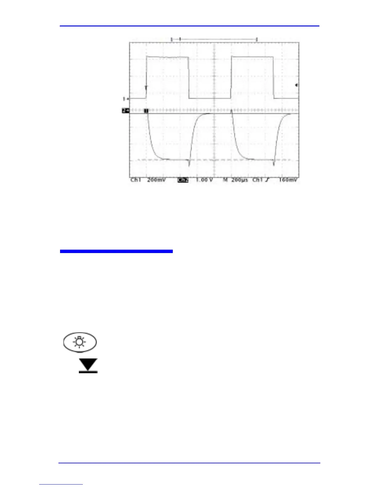
Figure 13: RED LED High Light Setting
Note: The peak-to-peak voltage tolerance includes a
possible probe impedance error.
Testing the IR LED
1. Turn on the signal generator.
2. Adjust the signal generator output until there is -475 to -
525 millivolts peak across the 10 ohm resistor (R1 in
Figure 11).
3. Select the Low Light setting on the SRC-MAX.
4. Measure the peak-to-peak voltage across the 1 meg ohm
resistor (R2 in Figure 11) on Channel 2 of the
oscilloscope. The peak-to-peak voltage should be 600 to
900 volts peak-to-peak . See Figure 14.