N10_Hardware_User_Guide
Copyright © Neoway Technology Co., Ltd.
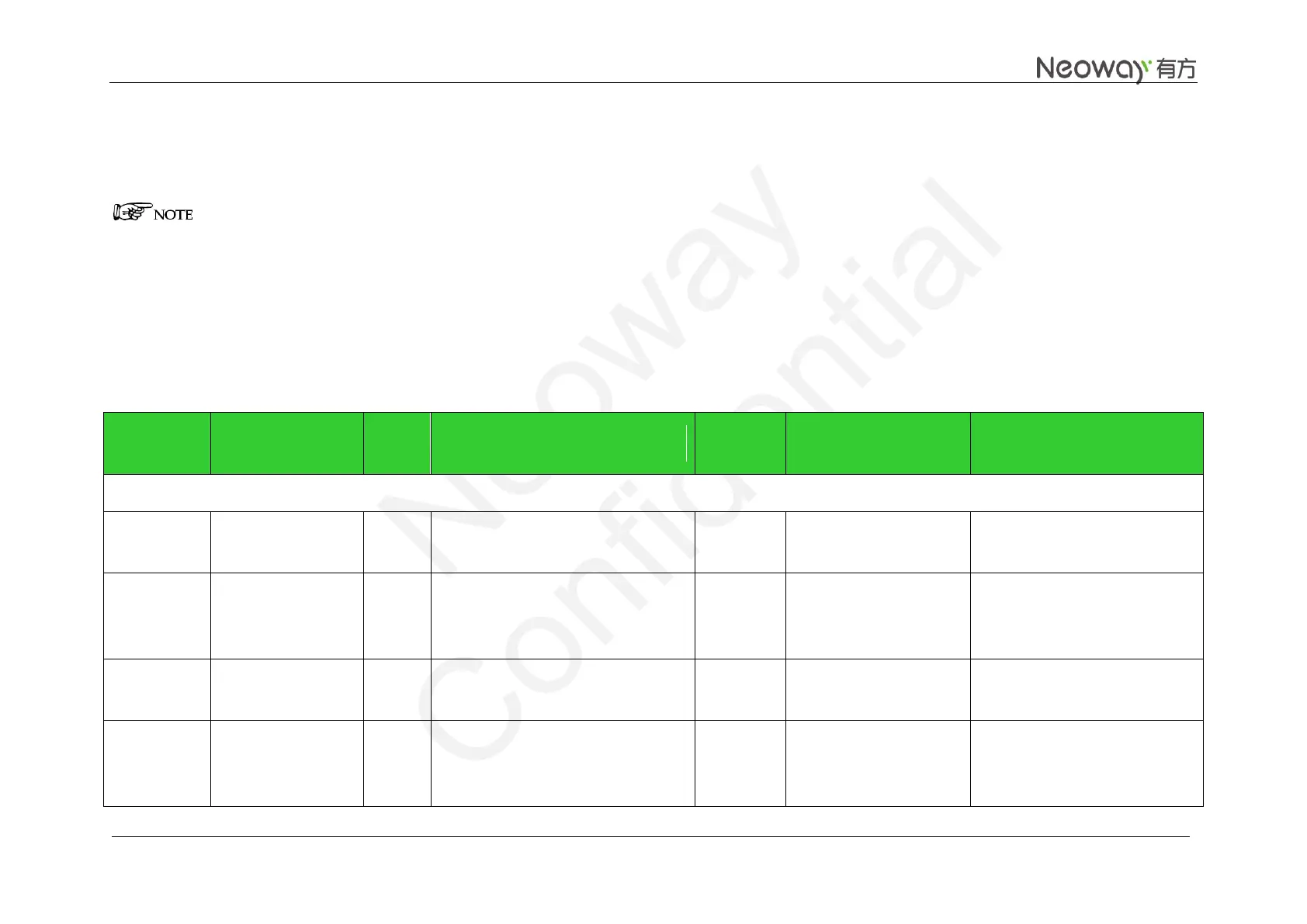
2.2 Pin Definition
P: indicates power supply pins
NC: indicates pins that are not supported and must not be connected
DI: indicates digital signal input pins
DO: indicates digital signal output pins
I/PD: indicates digital signal input pins with pull-down
I/PU: indicates digital signal input pins with pull-up
AI: indicates analogy signal input pins
AO: indicates analogy signal output pins
Table 2-2 N10 Pin definition
Electrical Level
Characteristics (V)
Power supply and Switch Interfaces
3.3 V to 4.3 V (3.9 V is
recommended)
2.8 V power supply output
Supply power for IO level
shifting circuit.
Load capability: less than 50 mA
2.8 V, maximum charging
output current 2 mA
1, 5, 20, 21,
32, 42, 44,
50, 52, 53, 64