N10_Hardware_User_Guide
Copyright © Neoway Technology Co., Ltd.
3.5 SIM Card
N10 module allows customers to embed one SIM card that supports M2M private networks, which
provide data service only. The embedded SIM card adopts QFN5*6 package. If the embedded SIM card is
used, do not connect the SIM card pins.
If the embedded SIM card is not used, design the SIM card circuit as described in the following.
Table 3-5 SIM card interfaces
Self-adaption to
1.8V/3.0V
SIM card power supply output
N10 supports 3.0 V and 1.8 V SIM cards. VSIM supplies power for SIM card with 30 mA.
SIM_IO is internally pulled up by a resistor. Add a 10 kΩ pullup resistor externally to VSIM if the trace is
long.
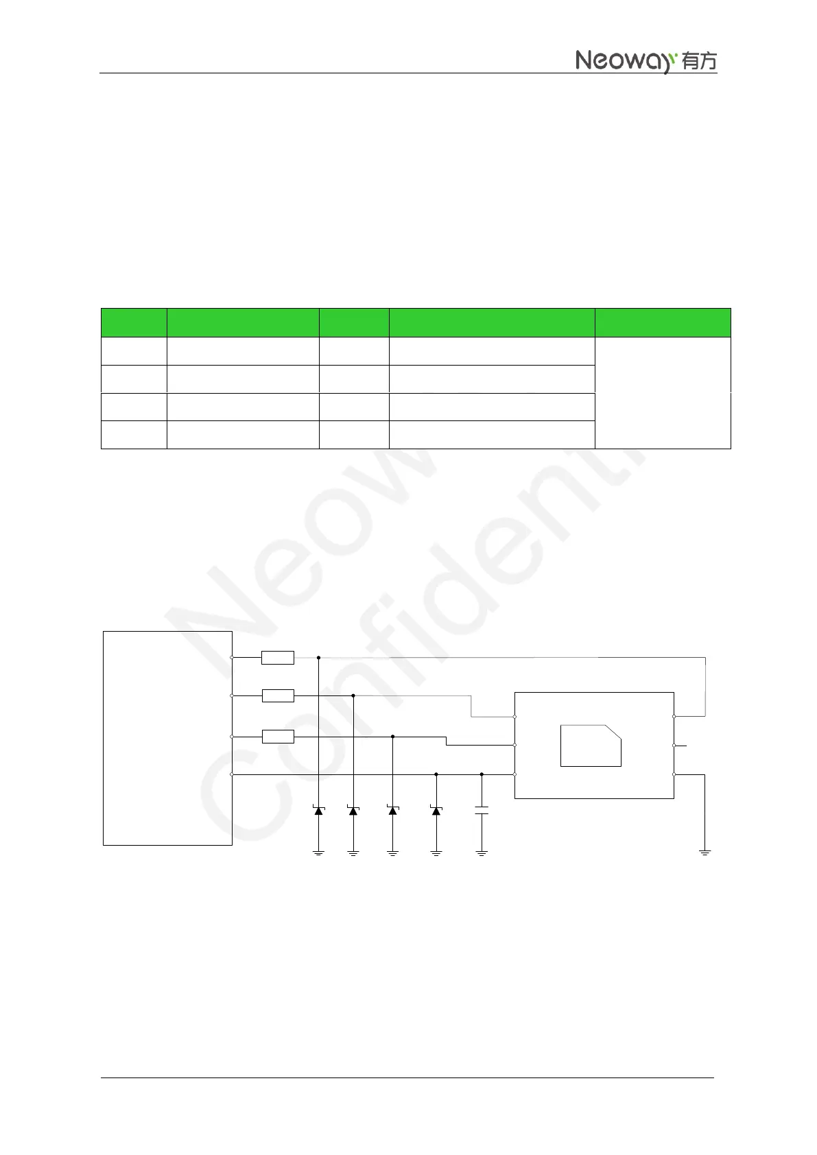
SIM_CLK can work at several frequencies at 3.25 MHz typically.
Figure 3-18 Reference design of SIM card interface
20
20
20
1 uF
SIM_IO
SIM_CLK
SIM_RST
VSIM
GPRS
Module
CLK
RST
VCC
VPP
GND
SIM Card
DATA
ESD protectors, such as ESD diodes (lower than 33 pF) or ESD varistors, are recommended on the SIM
signals, especially in automotive or other applications with bad ESD. In common applications, replace
ESD diodes with 27 pF to 33 pF grounding capacitors. The ESD diodes or small capacitors should be
close to SIM card.
If 6-pin SIM card socket is used, MCP-C713(H2.8) is recommended. Figure 3-19 shows its encapsulation.