N10_Hardware_User_Guide
Copyright © Neoway Technology Co., Ltd.
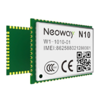
Figure 3-21 Reference design of MIC differential connections
GPRS module
33 pF
MIC
33 pF
100 pF
MIC_N
MIC_P
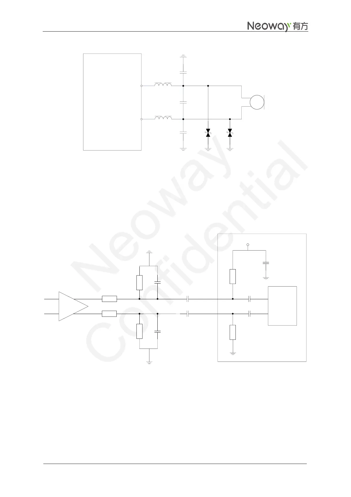
In Figure 3-22, a bias voltage for microphone is provided through MIC_P and MIC_N. But if an amplifier
is used between the microphone and module, capacitors like C1 and C2, should be placed between the
outputs of amplifier and module, to block the bias voltage.
For a peak voltage greater than 200 mV AC, an attenuation circuit comprised of R1-R4 should be used.
Figure 3-22 Reference design for common audio input
GPRS module
33 pF
33 pF
MIC_N
MIC_P
MIC_BIAS
Baseband
circuit
2.2 uF
2.2K
C1
C2
User’s
circuit
R1
R3
R2
R4
·
2.2K
R6
R5
In above figures, the audio input circuits are designed to meet the requirements for small audio signal, far
away from interference source and masking PCB routing by ground.
The maximum output power of SPK is 800 mW@8Ω.