N10_Hardware_User_Guide
Copyright © Neoway Technology Co., Ltd.
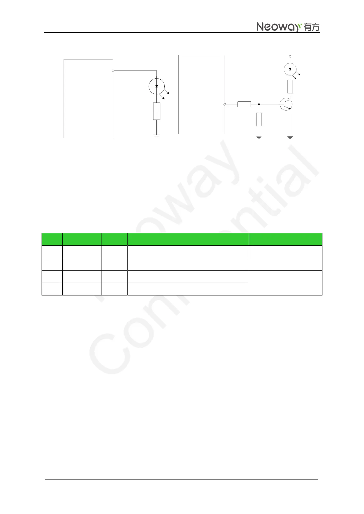
Figure 3-20 LED indicator
LIGHT
GPRS Module
10K
VCC
470
4.7K
When the module is running, the LED indicator is driven by the LIGHT to indicate different module
status with its various blink behaviors.
For how to set the LED indicator, see Neo_N10_AT_Commands_Mannual.
3.7 Audio
Table 3-7 Audio interface
Positive electrode of speaker
Negative electrode of speaker
Positive electrode of MIC
Negative electrode of MIC
N10 supports one input and output interface for audio. Audio volume can be adjusted via AT commands.
For details, see Neo_N10_AT_Commands_Mannual.
Figure 3-21 shows a reference audio interface design. The peak voltage routed to MIC should not exceed
200 mV AC. AGC circuit is integrated inside the module. Electret microphone is suited.
The module can meet the requirements of common handsets with AGC and volume control.