N10_Hardware_User_Guide
Copyright © Neoway Technology Co., Ltd.
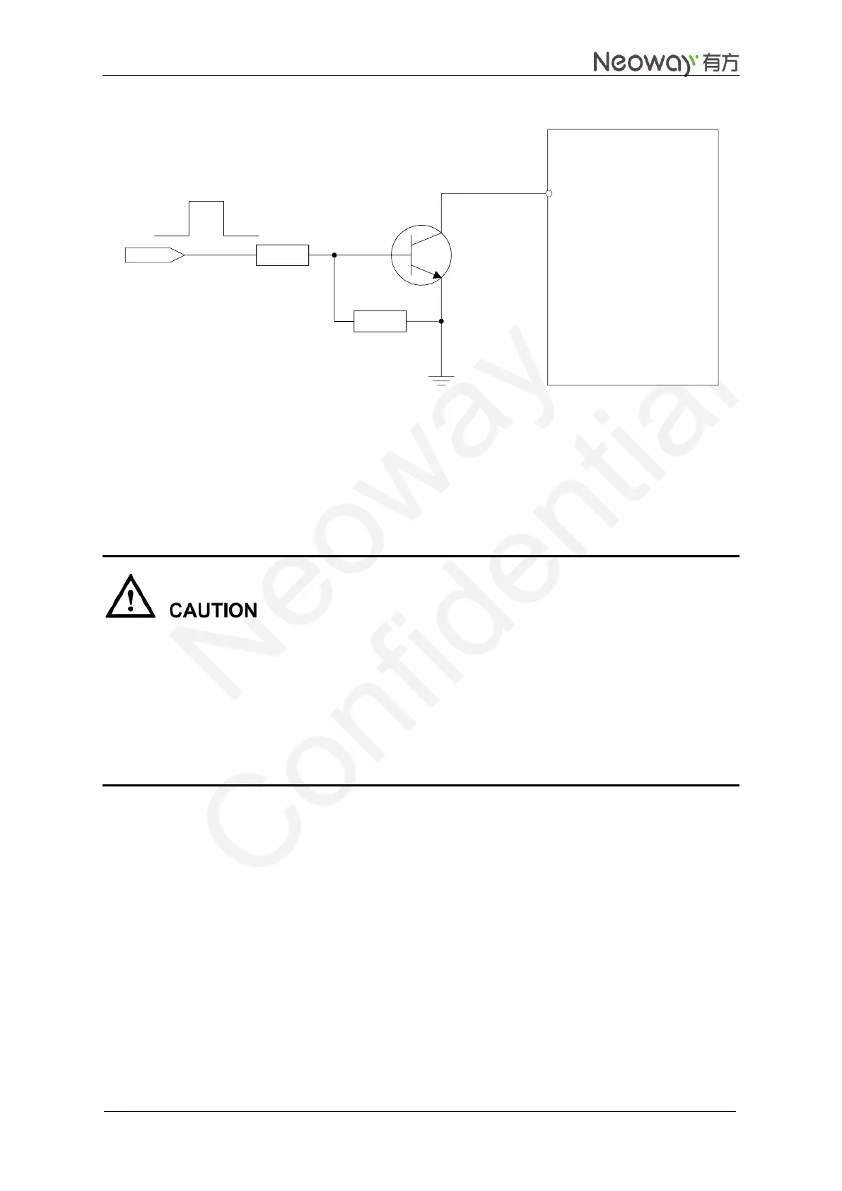
Figure 3-10 Reference circuit for power-on/off controlled by high level
USER_ON
GPRS Module
ON/OFF
4.7K
47K
R1
R2
In Figure 3-10, high level takes effect for ON/OFF on the user side (USER_ON) after level shifting.
R1 and R2 can be adjusted according to the driving capability of the USER_ON pin.
Use a common NPN transistor, e.g. MMBT3904; or a digital NPN transistor, e.g. DTC123. If digital
transistor is used, delete R1 and R2.
Level abnormalities at interfaces connected to the external MCU, especially the UART port, might
affect the power-on procedure of the module. For example, when a module is turned on, the IO ports
of the MCU are still in output status because they have not been initialized completely. The module
might fails to start if the UTXD signal (output pin) is forced to pull up or down.
The better way to rescue the module from abnormal condition is to apply a power OFF-ON
procedure, rather than using the ON/OFF control signal. In fact ON/OFF signal is
software-dependent.
3.1.5 RESET
Input low level for more than 100 ms at the RESET pin can reset the module. The pin is pulled up
internally by a resistor and the typical high level is 2.8 V. Leave the RESET pin unconnected if it is not
used.
RESET is a soft reset pin, but the RESET pin does not work when the module program runs off.
If 3.3 V IO system is used, separate it by adding a triode. Please refer to Figure 3-11.