N10_Hardware_User_Guide
Copyright © Neoway Technology Co., Ltd.
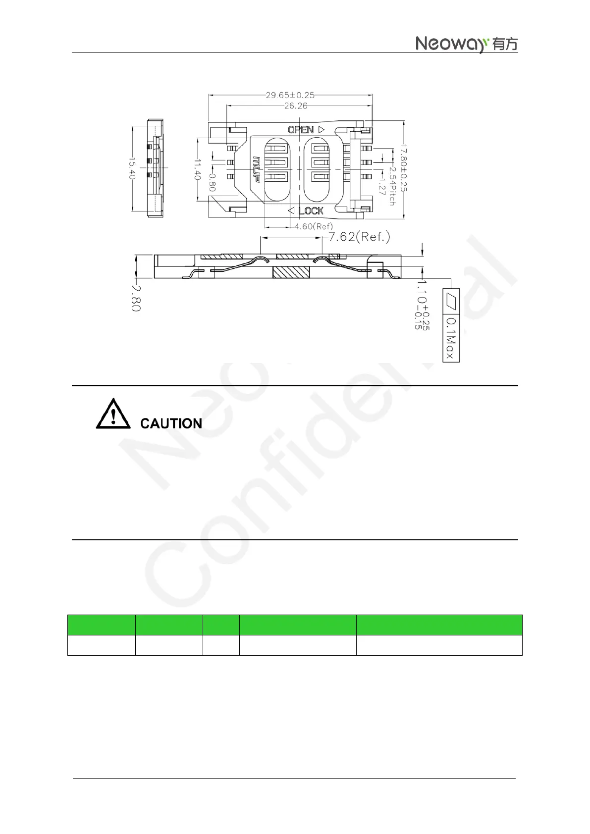
Figure 3-19 Reference of SIM card socket
SIM card is sensitive to GSM TDD noise and RF interference. So, the PCB design should meet the
following requirements:
The antenna should be installed far away from the SIM card and SIM card traces, especially to the
built-in antenna.
The SIM traces on the PCB should be as short as possible and shielded with GND copper.
The ESD diodes or small capacitors should be closed to SIM card on the PCB.
3.6 LIGHT
Table 3-6 LED indicator
The LIGHT pin can output a 4 mA of current and 2.8 V of voltage, therefore the LED can be directly
connected to this pin with a resistor in series. For better luminance, drive the LED with a transistor.