N10_Hardware_User_Guide
Copyright © Neoway Technology Co., Ltd.
3 Interface Design
3.1 Power Supply
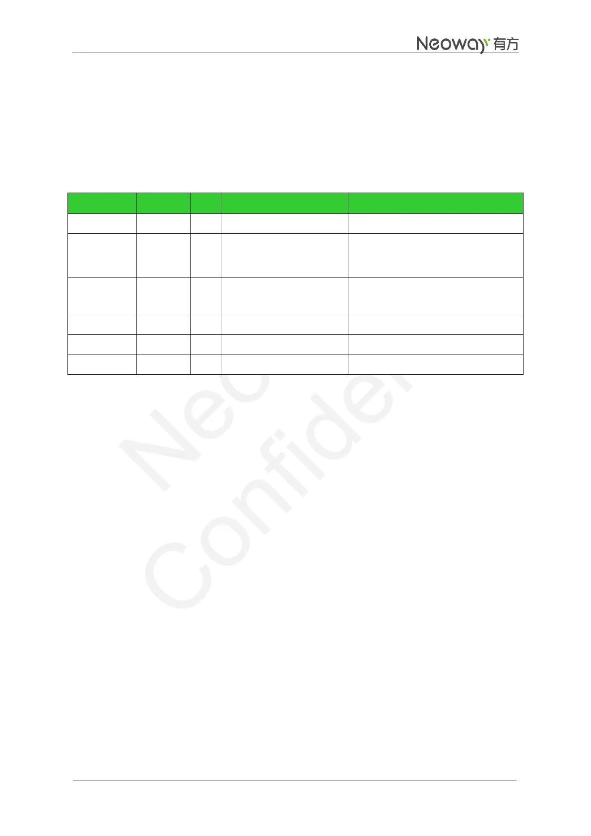
Table 3-1 Power supply and switch interface
3.3 V to 4.3 V (3.9 V is recommended)
1, 5, 20, 21,
32, 42, 44,
50, 52, 53, 64
2.8 V power supply output
Used only for level shifting
Loading capability < 50 mA
Low-level triggers ON/OFF state.
Low level triggers reset.
3.1.1 Design Requirements
VBAT is the power supply of the module. Its input voltage ranges from 3.3 V to 4.3 V and the typical
value is 3.9V. In addition to digital signals and analog signals, it supplies power to RF power amplifier.
The performance of the VBAT power supply is a critical path to module's performance and stability. The
peak input current at the VBAT pin can be up to 2 A when the signal is weak and the module works at the
maximum transmitting power. The voltage will encounter a drop in such a situation. The module might
restart if the voltage drops lower than 3.3 V.