N10_Hardware_User_Guide
Copyright © Neoway Technology Co., Ltd.
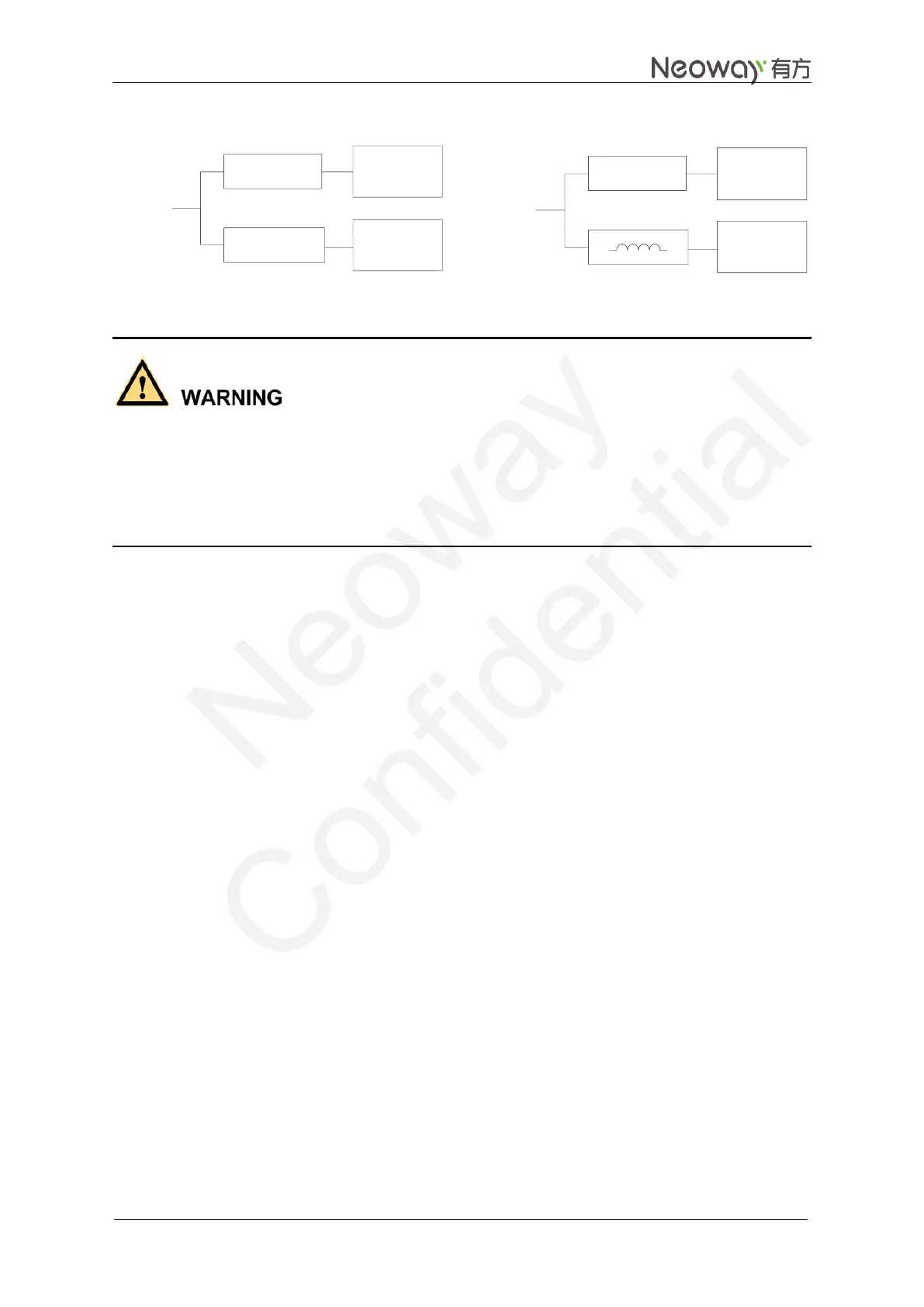
Figure 3-5 Reference designs of separated power supply
Other circuit
DC-DC/LDO
GPRS
module
DC-DC/LDO
Power
Input
Other circuitDC-DC/LDO
GPRS
module
Power
Input
10 uH
Reference Design (a) Reference Design (b)
Never use a diode to make the drop voltage between a higher input and module power. Otherwise,
Neoway will not provide warranty for product issues caused by this. In this situation, the diode will
obviously decrease the module performances, or result in unexpected restarts, due to the forward voltage
of diode will vary greatly in different temperature and current.
EMC Considerations
Place transient overvoltage protection components like TVS diode on power supply, to absorb the power
surges. SMAJ5.0A/C could be a choice.
3.1.2 VIO28
VIO28 outputs 2.8V@50 mA after the module is powered on. It is recommended that this interface is used
only for level shift. VIO28 stops output after the module is powered off.
3.1.3 VRTC
VRTC is the external power supply pin of RTC inside the module. It can be connected to external battery
or supercapacitor. When VBAT works properly, VRTC outputs 2.8 V and maximum 2 mA and can be
connected to current limiting resistor or supercapacitor to charge. When VBAT is disconnected, the
module can discharge the battery or capacitor to supply power for RTC in short time. Leave it
disconnected if not used.
Figure 3-6 shows the reference design of the VRTC power supply.