N10_Hardware_User_Guide
Copyright © Neoway Technology Co., Ltd.
The UART of N10 works at 2.8 V CMOS logic level. The voltages for input high level should not exceed
3.1 V. UART supports baud rates of 9600, 14400, 19200, 38400, 57600, 115200 bit/s, and the default rate
is 115200 bit/s.
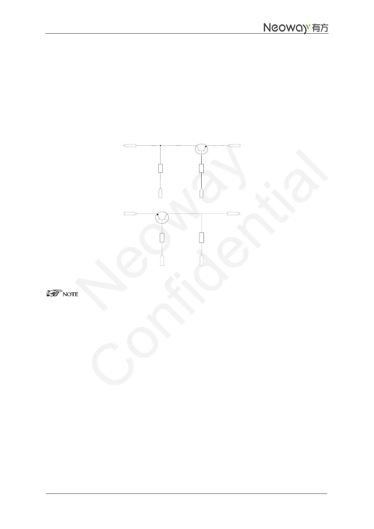
If the UART does not match the logic voltage of the MCU, add a level shifting circuit outside of the
module as shown in Figure 3-13 (for V
OL_MAX
≤200 mV) and Figure 3-14 (for V
OL_MAX
>200 mV).
Figure 3-13 Recommended level shifting circuit 1
TXD
VIO28
VCC_IO
4.7K
10K
Q1
R2
R3
MCU_URXD
MCU_UTXD
Q2
RXD
10K
R1
4.7K
R4
VIO28
VIO28
Components:
R2/R4: 2 kΩ-10 kΩ. The greater the UART baud rate is, the lower the R2 value is.
R1/R3: 4.7 kΩ-10 kΩ. The greater the UART baud rate is, the lower the R3 value is.
Q1: MMBT3904 or MMBT2222 High-speed transistor is better.
MCU_UTXD and MCU_URXD are respectively the TX and RX ports of the MCU while UTXD and
URXD are respectively the TX and RX ports of the module.
Voltage at VCC_IO is the voltage at the UART of the MCU while voltage at VIO28 is the voltage at the
UART of the module.
Figure 3-14 shows another recommended level shifting circuit.