N10_Hardware_User_Guide
Copyright © Neoway Technology Co., Ltd.
MIC29302WU in the following figure is an LDO and outputs 3 A current to ensure the performance of the
module.
Figure 3-3 Reference design of power supply control
VCC_IN_5V
GPRS_EN
VBAT
100 uF
TAN
0.1 uF
TVS
5V
10 uF
470uF
TAN
10K
4.75K
VOUT
MIC29302WU
EN
VIN ADJ
0.1 uF
100pF
33pF
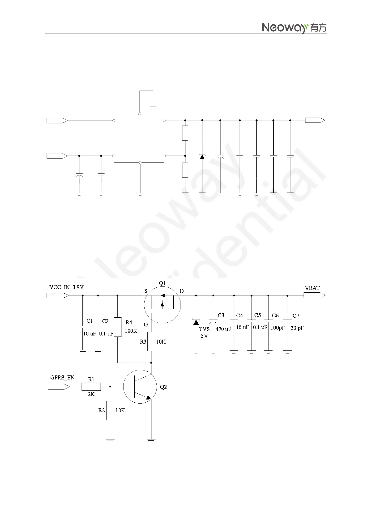
The alternative way is to use a p-MOSFET to control the module's power, as shown in Figure 3-4.
When the external MCU detects the exceptions such as no response from the module or the disconnection
of GPRS, power off/on can rectify the module exceptions.
In Figure 3-4, the module is powered on when GPRS_EN is set to high level.
Figure 3-4 Reference design of power supply controlled by p-MOSFET