N10_Hardware_User_Guide
Copyright © Neoway Technology Co., Ltd.
The USB interface of N10 module can be used to download software. Before that, connect USB interface
to a computer and then power on the module.
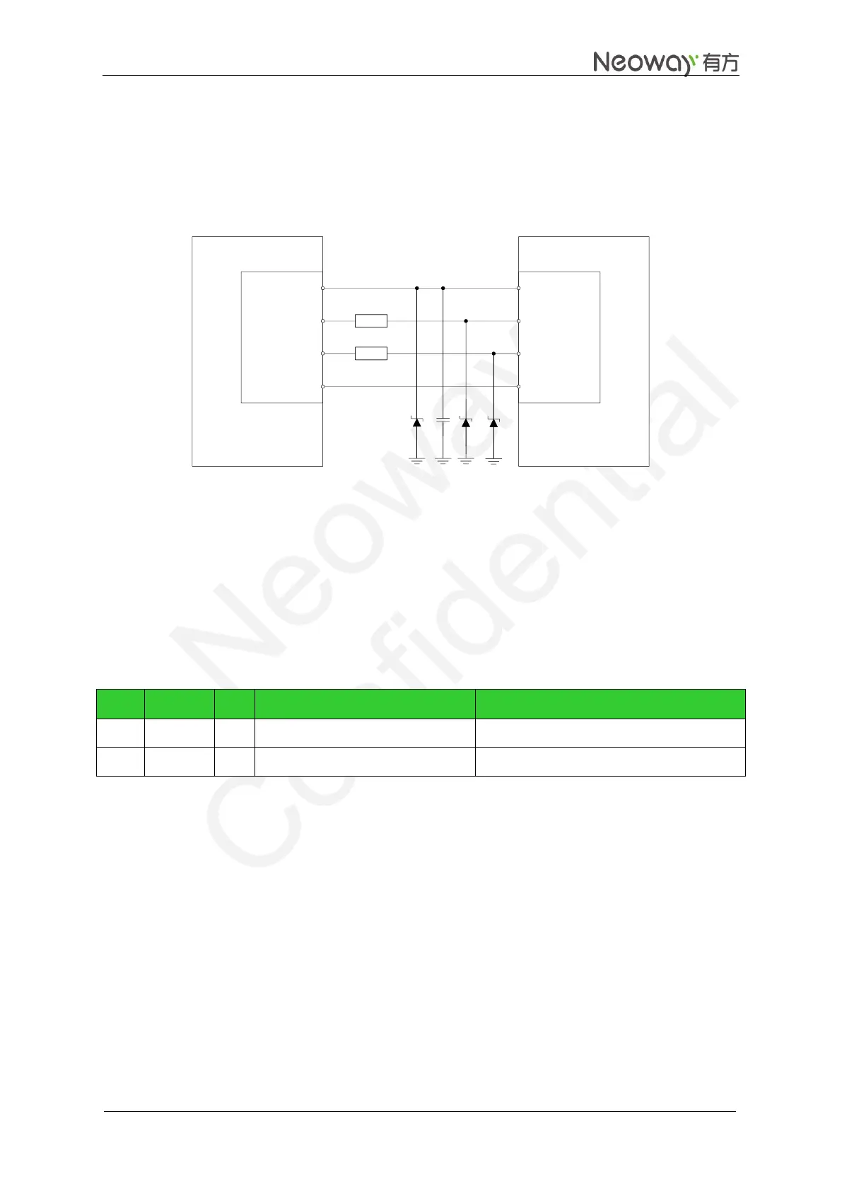
Figure 3-15 shows the recommended connection between the module and a computer.
Figure 3-15 USB circuit
GPRS
Module
VBUS
USB_DM
USB_DP
GND
PC
UTXD
URXD
RTS
CTS
VBUS
USB_DM
USB_DP
GND
20
20
Connect a 1 μF filter capacitor in parallel to VBUS and place it as close to the pin as possible. Add TVS to
the VBUS power cable. Use TVS diodes with a capacity of lower than 12 pF for protection on the data
cables of USB_DP and USB_DM, and adopt differential signal trace for USB_DP and USB_DM.
3.4 DTR and RING
Table 3-4 DTR and RING pins
Signal for controlling sleep mode
Leave this pin unconnected if it is not used
Leave this pin unconnected if it is not used
3.4.1 DTR Pin
Generally DTR is used to control sleep mode together with AT commands. For details, see Neo_N10_ AT
Commands_Mannual. Based on the setting of the selected mode, pulling DTR low will bring the module
into sleep mode if the module is idle. In this mode, the idle current is less than 2 mA, depending on the
DRX setting of network.
In sleep mode, the module can respond to the incoming call, SMS, and GPRS data. The host MCU can
also control the module to exit sleep mode by controlling DTR.
Process of entering the sleep mode: