Physical Description 2-1
Chapter 2
Physical Description
This chapter describes the hardware features of the NETGEAR Model FS562 and FS566 Fast
Ethernet Fiber Switches.
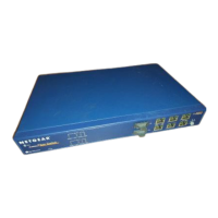
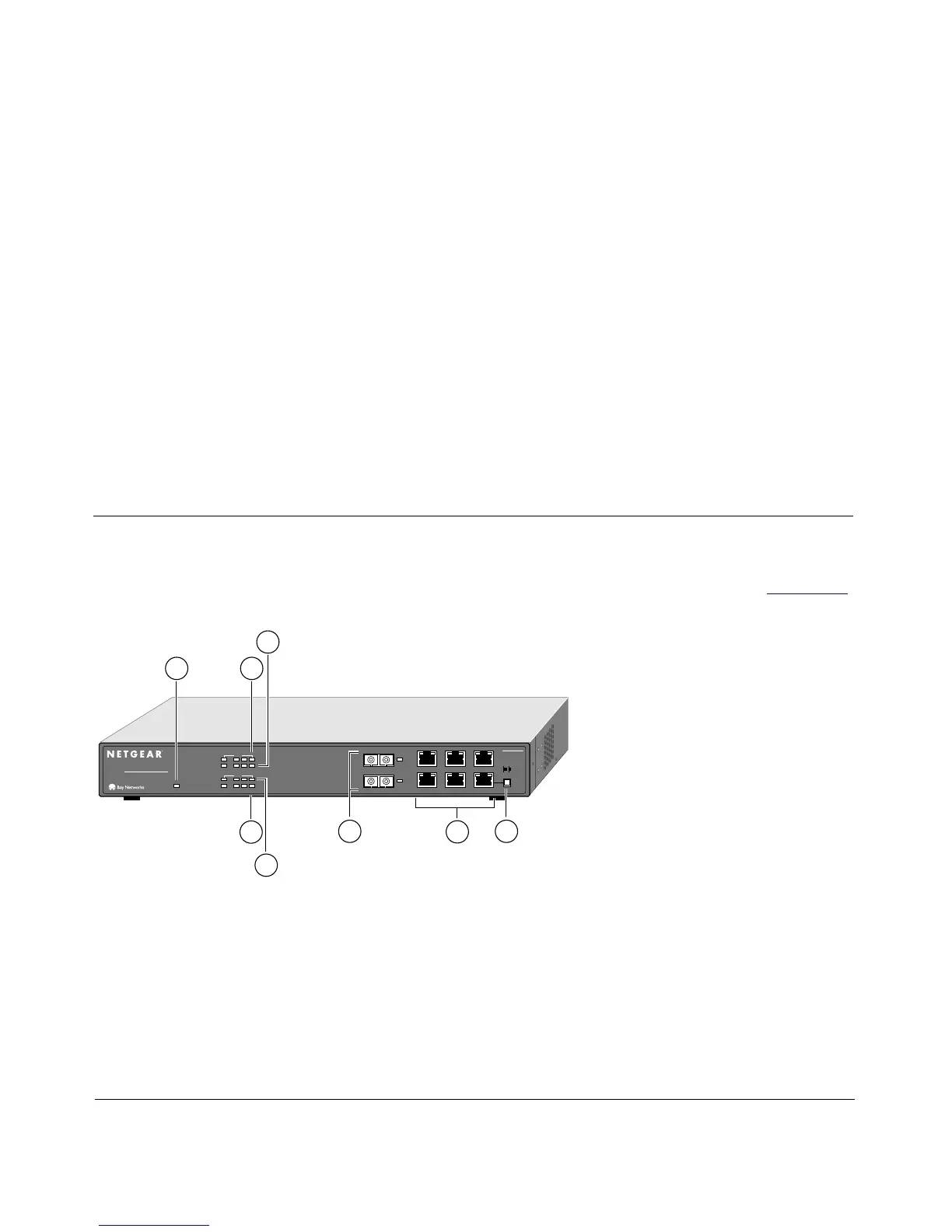
Front Panel
For easier management and control of the Model FS562 switch, familiarize yourself with the ports,
LEDs, and Normal/Uplink push button on the front panel of the switch, as illustrated in Figure 2-1.
Key:
1 = Power LED
2 = RX/TX LEDs for ports 1 (fiber), 3, 4, and 5 (UTP)
3 = FDX/COL LEDs for ports 1 (fiber), 3, 4, and 5 (UTP)
4 = FDX/COL LEDs for ports 2 (fiber), 6, 7, and 8 (UTP)
5 = RX/TX LEDs for ports 2 (fiber), 6, 7, and 8 (UTP)
6 = 100 Mbps fiber ports 1 and 2 with 100M Link LEDs next to each port
7 = 10/100 Mbps UTP ports with 10M or 100M Link LEDs on each port
8 = Normal/Uplink push button for port 8
Figure 2-1. Front Panel of the Model FS562 Switch
Normal/Uplink
On = Link100M
Link
Link
10M
6
3
5
2
4
2
1
1 123
FS562
MODEL
Fiber Switch
8
PORT
10/100Mbps
Green = FDX, Yellow = COL
Rx/Tx
Power
2
3
1
86
7
4
5
1
2456
Green = FDX, Yellow = COL
Rx/Tx
8883FA