Installation Guide for the Model FS562 and Model FS566 Fiber Switches
2-4 Physical Description
100BASE-FX Fiber Ports
The Model FS562 switch has two 100BASE-FX fiber ports; the Model FS566 switch has six.
These ports operate at 100 Mbps exclusively and provide a standard duplex SC connector for
62.5/125
-
P
m
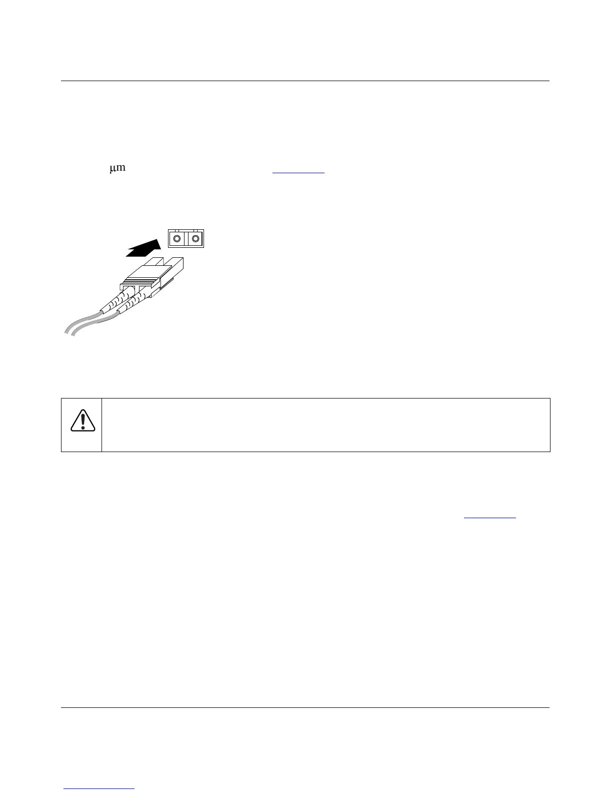
multimode fiber optic cable. Figure 2-4 shows a fiber optic cable connection to a
duplex SC connector. For further information about fiber optic cables and connectors, refer to
Appendix B, “Connector Pin Assignments,” and Appendix C, “Cabling Guidelines.”
Figure 2-4. 100BASE-FX Fiber Connection
Normal/Uplink Push Button
The Normal/Uplink push button on the front panel of the switch, as illustrated in Figure 2-1,
allows you to select uplink (MDI) or normal (MDI-X) wiring for port 8 on the Model FS562 Fiber
Switch or port 12 on the Model FS566 Fiber Switch. This port is configured for normal wiring to
connect to a PC when the push button is in the out position. When the push button is pressed in,
this port is configured for uplink wiring to connect to another switch or to a hub, using a
straight-through twisted pair cable.
Warning:
Fiber optic equipment can emit laser or infrared light that might injure your
eyes. Never look into an optical fiber or connector port. Always assume that fiber optic
cables are connected to a light source.
8806FA