Installation Guide for the Model FS562 and Model FS566 Fiber Switches
2-2 Physical Description
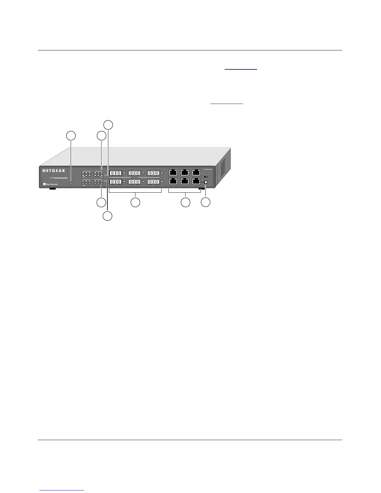
The front panel of the Model FS566 switch, as illustrated in Figure 2-2, is almost identical to that
of the Model FS562 switch. The main difference is the number of fiber ports and corresponding
LEDs. The Model FS566 switch has six fiber ports, and the Model FS562 switch has two.
The front panel of the Model FS566 switch is shown in Figure 2-2
.
Key:
1 = Power LED
2 = RX/TX LEDs for ports 1, 2, and 3 (fiber) and ports 7, 8, and 9 (UTP)
3 = FDX/COL LEDs for ports 1, 2, and 3 (fiber) and ports 7, 8, and 9 (UTP)
4 = FDX/COL LEDs for ports 4, 5, and 6 (fiber) and ports 10, 11, and 12 (UTP)
5 = RX/TX LEDs for ports 4, 5, and 6 (fiber) and ports 10, 11, and 12 (UTP)
6 = 100 Mbps fiber ports 1 through 6 with 100M Link LEDs next to each port
7 = 10/100 Mbps UTP ports with 10M or 100M Link LEDs on each port
8 = Normal/Uplink push button for port 12
Figure 2-2. Front Panel of the Model FS566 Switch
Normal/Uplink
On = Link100M 10M
6
3
5
2
4
6
1
Link
100M Fiber
Link
123 123
FS566
MODEL
Fiber Switch
12
PORT
10/100Mbps
Green = FDX, Yellow = COL
Green = FDX, Yellow = COL
Rx/Tx
Rx/Tx
456 456
Power
6
2
3
1
8
7
4
5
54
321
8881FA