Installation Guide for the Model FS562 and Model FS566 Fiber Switches
2-6 Physical Description
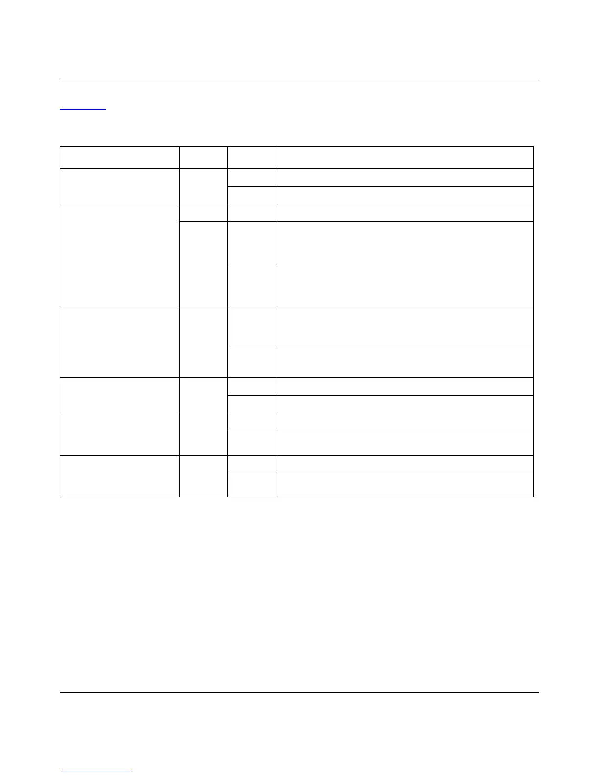
Table 2-1 describes each LED on the front panel of the Model FS562/FS566 switch.
Table 2-1. LED Descriptions
Label Color Activity Description
Power Green On Power is supplied to the switch.
Off Power is disconnected.
FDX/COL Green On A full-duplex link is established on the port.
Yellow On A half-duplex link is established on the port, and the port
is experiencing collisions (note that occasional collisions
are normal).
Off No full-duplex link is established, or no collisions are
occurring on the port when operating in half-duplex
mode.
RX/TX Green Blinking Packet transmission or reception is occurring on the port.
The blinking action corresponds to the number of
packets that are transmitted or received.
Off No packet transmission or reception is occurring on the
port.
Link (located to the right
of each fiber connector)
Green On A valid 100 Mbps link is established on the port.
Off No link is established on the port.
100M Link (located at the
top left corner of each
10/100 Mbps UTP port)
Green On A valid 100 Mbps link is established on the port.
Off No 100 Mbps link is established on the port.
10M Link (located at the
top right corner of each
10/100 Mbps UTP port)
Green On A valid 10 Mbps link is established on the port.
Off No 10 Mbps link is established on the port.