Figures vii
Figures
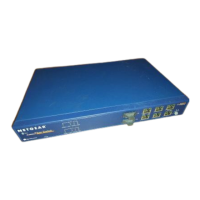
Figure 2-1. Front Panel of the Model FS562 Switch ...................................................2-1
Figure 2-2. Front Panel of the Model FS566 Switch ...................................................2-2
Figure 2-3. The Vista RJ-45 Connector with Built-In LEDs ........................................2-3
Figure 2-4. 100BASE-FX Fiber Connection ...............................................................2-4
Figure 2-5. Rear Panel of the Model FS562 Switch ...................................................2-7
Figure 2-6. Rear Panel of the Model FS566 Switch ...................................................2-7
Figure 3-1. Using the Model FS562 Switch for Desktop Switching ............................3-2
Figure 3-2. Model FS562 and Model FS566 Switches Used as Segment Switches ..3-3
Figure 3-3. Using the Model FS562 and Model FS566 Switches for
Extension ..............................................................................................3-4
Figure 3-4. Bridging 10 Mbps Networks to 100 Mbps Networks ................................3-5
Figure 3-5. High-Bandwidth File Server Connection ..................................................3-6
Figure 4-1. Attaching Mounting Brackets to the Model FS562/FS566 Switch ............4-3
Figure B-1. RJ-45 Plug and Vista RJ-45 Connector with Built-In LEDs ..................... B-1
Figure B-2. Duplex SC Connector and Duplex SC Plug Connection ......................... B-2
Figure C-1. Straight-Through Twisted Pair Cable ....................................................... C-3
Figure C-2. Crossover Twisted Pair Cable .................................................................C-3
Figure C-3. Category 5 UTP Patch Cable with Male RJ-45 Plug at Each End .......... C-4