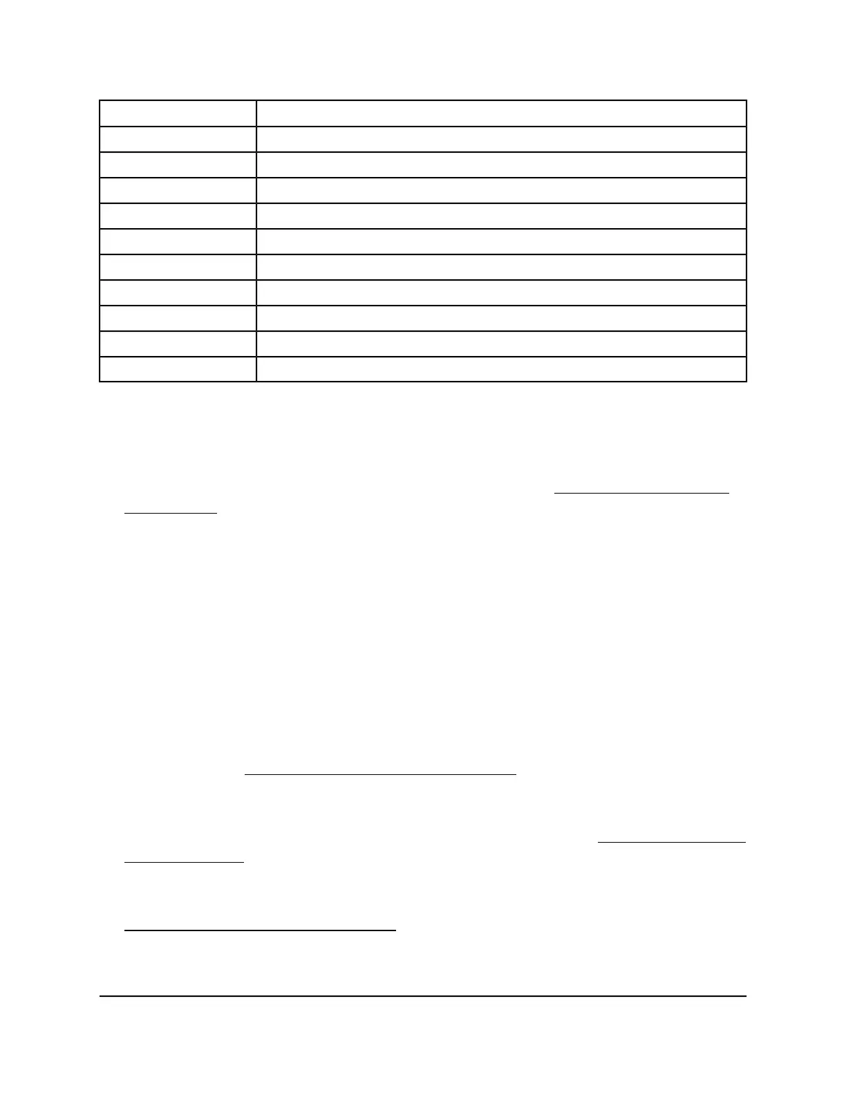
DescriptionNumber
Power 1, Power 2, and Fan LEDs1
Stack ID LED2
USB port3
RJ-45 RS232 console port4
Stack Master LED5
Reset button6
Mini USB console port7
OOB port with port LEDs8
10GBASE-X SFP+ ports, each with a port LED9
10GBASE-T ports, each with a port LED10
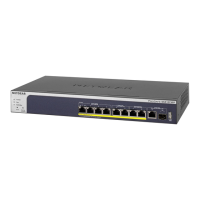
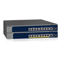
Common components
From left to right, the front panel of the full 10G models provides the following
components:
•
Power, Fan, Stack Master, and Stack ID system LEDs (see LEDs, M4300 series full
10G models on page 21) .
Because model M4300-24X24F can support two PSUs, the front panel provides both
a Power 1 LED and Power 2 LED.
•
Recessed Reset button.
•
One mini USB console port.
•
One USB 2.0 port.
•
One RJ-45 RS232 (115200, N, 8, 1) console port (models M4300-16X, M4300-8X8F,
and M4300-24X24F).
On model M4300-12X12F, the RJ-45 RS232 console port is on the back panel.
•
One out-of-band (OOB) 1G Ethernet port (models M4300-16X, M4300-8X8F, and
M4300-24X24F) with a left LED that indicates the speed and a right LED that indicates
the activity (see LEDs, M4300 series full 10G models on page 21).
On model M4300-12X12F, the OOB 1G Ethernet port is on the back panel.
•
Depending on the model, eight, twelve, or twenty-four independent 10GBASE-X
SFP+ ports, each with a combined speed and activity LED (see LEDs, M4300 series
full 10G models on page 21).
•
Depending on the model, eight, twelve, sixteen, or twenty-four independent
10GBASE-T autosensing ports, each with a combined speed and activity LED (see
LEDs, M4300 series full 10G models on page 21).
Hardware Installation Guide18Hardware Overview
M4300 Intelligent Edge Series Fully Managed Stackable Switches
 Loading...