Set up
5-8
N
Once you have pressed [ent] to complete an entry, you can
press [ce] to take you back one step at a time.
Linear error compensation
In this mode, you can apply a single constant correction factor
for each axis to all displayed measurements. You calculate the
correction factor, and specify it in parts per million (ppm). The
values can be between
−9999 and +9999.
In this mode a single constant correction factor for each axis is
applied to all displayed measurements.
If you set one or more axes to Linear Error Compensation,
then you need to carry out the following procedure to configure
the compensation for each of those axes.
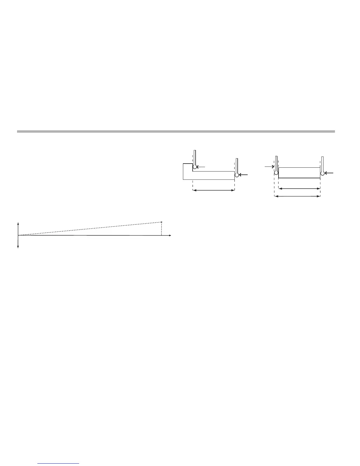
Calculating the correction factor
As you follow the procedure you must ensure that you either use
a stepped standard, and approach each edge from the same
direction; or if you must approach each edge from opposite
directions, then subtract the width of the tool or measuring probe
from the value displayed on the C80.
For example: To check the scale against a standard which is
exactly 500mm wide:
1. Set the tool or probe to one edge of the standard, and press
the Select Key for the axis that you need to correct.
The display shows ‘0.000’.
2. Set the tool or probe to the other edge of the standard.
The display shows ‘499.800’.
3. Calculate the correction factor:
error = 500.000
− 499.8 = 0.2mm
Correction Factor = error/standard = 0.2/500 x 1,000,000 =
+400 ppm (parts per million)
For this example you need to increase the value displayed on
the C80 to match the standard, as this is a positive correction
factor. If the display had shown 500.2 for the same standard, the
correction factor would be negative,
−400 ppm.