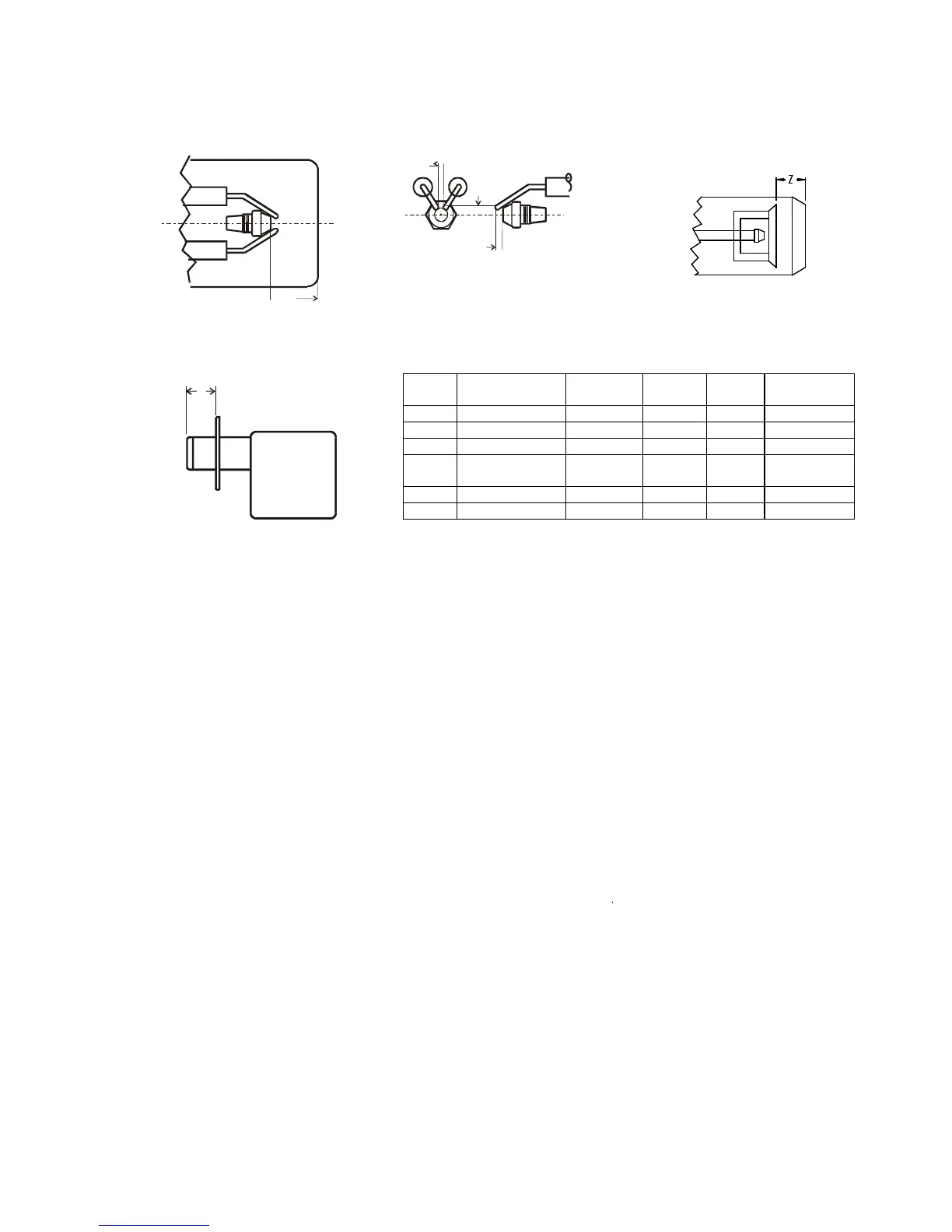
ELECTRODE SETTINGS
FIG 6A FIG 6B FIG 6C
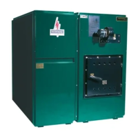
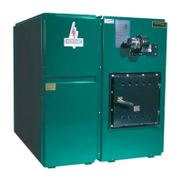
FIG 7 BURNER INSERTION TABLE 6 DIMENSIONAL RELATIONSHIPS (Figs 6 & 7)
`
Use burner manufacturer’s gauge if supplied.
OIL FILTER
Use a 10 micron or better filter. We recommend an additional in-line filter. The oil filter should be cleaned
or replaced at least once a year by the serviceman.
OIL PUMP AND FUEL SYSTEM
Make sure the by-pass plug is correctly located for a one or two pipe system. Failure to do so may
damage the pump. Generally, for 3/8” copper tubing, the vertical lift should not exceed 8 feet and the
horizontal run should be limited to 30 feet. Do not exceed 10 psi inlet line pressure.
Single pipe systems are recommended for gravity feed or when the tank outlet is at a higher elevation
than the pump inlet. Refer to Fig. 10. The inlet vacuum should be no more than 6" Hg.
Two pipe systems are recommended for lift feed or when the pump inlet is at a higher elevation than the
tank outlet. Install the return line termination higher than the supply intake as shown in Fig. 10. Generally,
the inlet vacuum should be no more than 12" Hg.
Correct piping is critical to long-term operation of the fuel system. Never use compression fittings.
Minimize the resistance to flow due to excessive line lengths; high lift; and unnecessary fittings, kinks and
bends. This will decrease the running vacuum and the risk of air separation. A “Tigerloop” fuel oil de-
aerator may improve the performance of poorly designed fuel oil delivery systems.
Riello 40 or BF Beckett Std.
Head
Beckett
Adj. Head
Aero Carlin
A 5/32” 5/32” 5/32” 1/8” 1/8” to 5/32”
B 13/64” 7/16” 7/16” 7/32” 5/16”
C 5/64” to 7/64” 1/16” 1/16” 1/8” 1/16”
Z Refer to Turbulator
Setting
1-1/8”
(Fig 6A)
1-3/4”
(Fig 6C)
1-1/8”
(Fig 6A)
Use Positioning
Bar
E - NH3 4-5/8” 5” 5” 5” 5”
E - LFR 2” 2-3/8” 2-3/8” 2” 1-1/2”
Z