PROPER DUCT SIZING
Locate the furnace as close as possible to the center of the heat distribution system and make sure the
top is level. Refer to TABLES 6 and 7, DUCT SIZING FOR HEATING and COOLING in this manual.
AIR CONDITIONING
This appliance is designed to accommodate air conditioning equipment. A/C ready models incorporate a
fan center transformer / relay. Live motor leads must be isolated on direct drive motors using a two speed
fan & limit control or a suitable fan center control.
HUMIDIFIER
If a humidifier is installed, ensure water cannot drip on the heat exchanger. This will damage the furnace
and void the warranty.
ELECTRICAL CONNECTIONS
The NH3-4 furnace is rated at 120V, 60Hz, 1-Phase, 20 Amp fuse.
The LFR and NH3 furnaces are rated at 120V, 60Hz, 1-Phase, 15 Amp fuse
See the furnace marking label. Follow the National Electrical Code as well as provincial, state, and local
regulations. Figs. 13, 14 and 15 show standard wiring schematics.
FUEL SYSTEMS
Fuel not heavier than No. 2 fuel oil must be used. The oil supply tank must be of a listed or certified type
acceptable to the regulatory authority having jurisdiction. Install the oil tank or tanks according to local codes
and regulations. The tank should be kept at least 1/4 full. If a two-pipe system is used, suction and return lines
should be of the same diameter and extend to the same depth in the tank. An emergency oil shut-off valve
should be installed as required by local ordinance. This can be manual, electric solenoid, or vacuum operated.
An oil safety valve that cuts the fuel supply unless a vacuum is created by the pump is recommended. Any
leaks in the system will prevent oil from flowing. Suntec PRV or Webster OSV valves are recommended.
Loop copper lines connected directly to the oil pump to reduce vibration. Use separate oil line for each
individual appliance to prevent “loss of prime” problems.
THERMOSTAT
Locate the thermostat on an interior wall free from drafts approximately 5 feet above floor level. The operation
of the burner is normally controlled by the room thermostat, which may be set for the temperature desired,
typically 70°F. if a higher or lower temperature is desired, the indicator should be set to the proper point on the
scale.
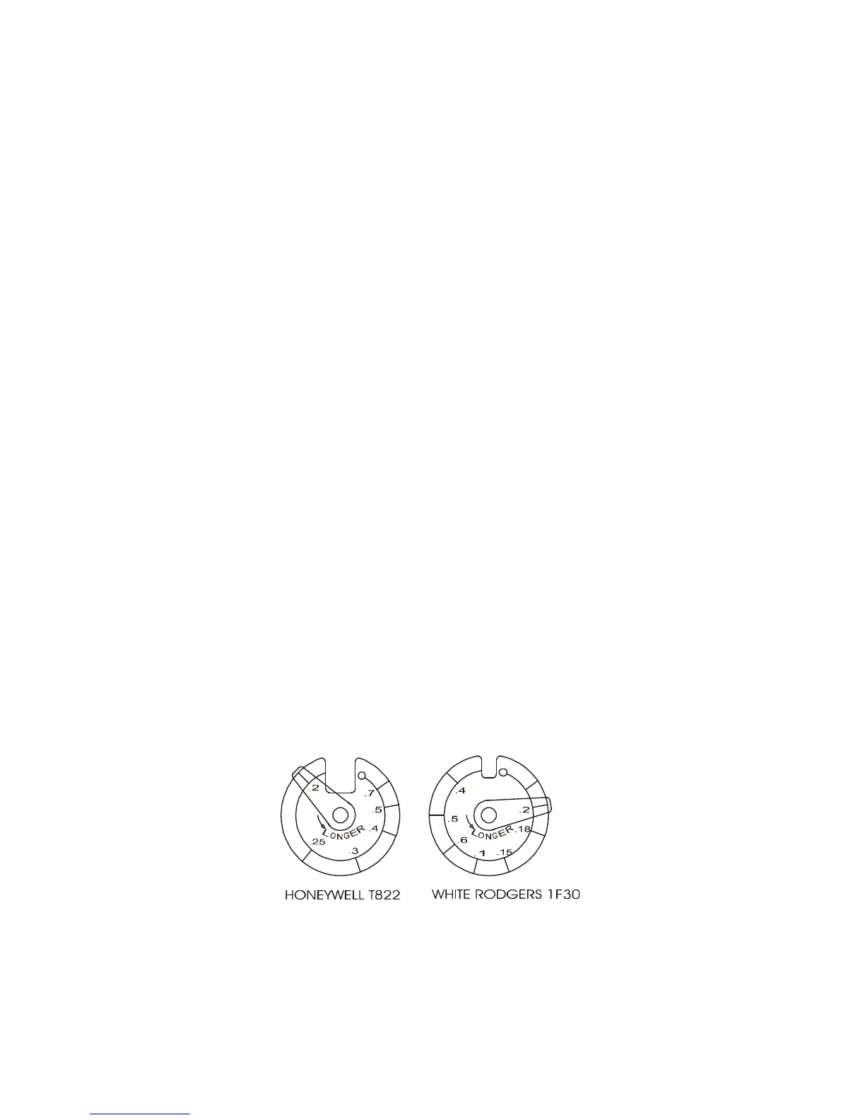
THERMOSTAT HEAT ANTICIPATOR
To prevent short cycling, the heat anticipator should be set as recommended in the specifications for the burner
primary control. This is typically set at 0.1 or 0.2 amps as indicated in Figure 1. This adjustment changes the
thermostat’s response time to prevent the room temperature from over-running the thermostat setting.
FIG. 1 - Heat Anticipator
WARNING: The heat anticipator will BURN OUT if 25 volts are applied directly to the thermostat by
shorting out the primary control during testing or incorrect wiring. If this happens the thermostat
warranty is void.