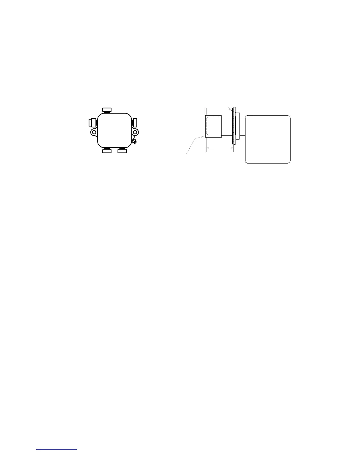
BURNER OIL PRESSURE CHECK
Install the pressure gauge directly on the gauge or nozzle port. Adjust to the pressure specified by
Newmac for the nozzle input rating. Refer to TABLE 1 (NH3) or 3 (LFR),
GENERAL INSTRUCTIONS
in
this manual or the certification label on the appliance.
Each oil burner should have its own suction line. A common return line can be used as long as the
diameter is large enough. Check valves are not required on properly installed systems. Service on fuel
units should not be attempted without a suitable vacuum and pressure gage.
The oil piping information presented here is intended as a guide only. For piping system design
data, consult the installation instructions from the pump manufacturer.
FURNACE SET UP AND MAINTENANCE
BLOWER MOTORS
Motor manufacturers supply some motors that do not require oiling. Oil ports usually have plastic covers
and are found on the motor end caps. If oil ports are not incorporated, oiling is not required. For motors
with provision for re-oiling use SAE 20 non-detergent oil or oil specially formulated for electric motors.
Use only a few small drops two or three times a year.
COMBUSTION CHAMBER
For the NH3, make sure the cerafelt combustion chamber was not damaged or mis-aligned during
shipping. Inspect the combustion chamber periodically and replace if necessary. The LFR has no cerafelt
combustion chamber.
SMOKE BAFFLES
Both the NH3 and the LFR furnaces have factory installed smoke baffles inside the radiator ducts.
NH3 - Check to ensure they have not become dislodged during shipping. They can be checked and
repositioned, if necessary, by reaching in through the breech pipe and pushing them down the tubes so
their stop tabs are flush against the welds.
LFR – The baffles are accessed through the front cleanout covers. No adjustment is normally necessary.
AIR FILTER RACK
NH3 - The air filter rack can be positioned on the left or right.
NH3-4 - The filter racks shipped with the furnace mount on both sides. Knockouts are provided at the
corners to cut the opening. The opening in the rack for sliding in the filters should face the front of the
furnace, unless there is there is enough clearance at the rear to change the filters without damage — at
least 24 inches.
LFR – See FIG. 12. The air filter rack can be positioned on the left or right, rear or base of the blower
compartment. The left and right openings are already cut; the one which is not in use is covered by a side
panel. If a rear or base opening is required it should be cut (17-3/4” x 13-3/4”). An additional side cover
can be obtained from Newmac to cover the unused side opening.