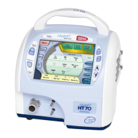
Figure F-2 Symbols Version- Front Panel Overview
OPRHT70 A0310
F-2
1. Breath Delivery Indicator. LED flashes green with every breath delivered by the
ventilator.
2. External Power LED. Lights green whenever external power is connected. This
also indicates that the Integrated Battery System is being charged.
3. Manual Inflation button. Press and hold this button to deliver flow to the patient.
The ventilator will deliver flow at the current settings while the button is pressed.
Flow delivery is limited to a maximum of 3 seconds or until the High Pressure
alarm setting is reached.
4. Brightness button. Press this button repeatedly to scroll to one of four screen
brightness levels.
5. Device Alert LED. Lights red when there is a device alarm. Take the ventilator out
of service and use an alternate means of ventilation until resolved.
6. Patient Gas Outlet. Attach patient breathing circuit tubing here.
7. Exhalation Valve Drive Tubing connector. Attach exhalation valve drive tubing here.
8. Proximal Pressure Line connector. Attach proximal pressure tubing here.
9. Alarm Violation LEDs. LEDs in the handle light to indicate alarm conditions.
10. Alarm Silence/Reset button. Press this button to silence the audible alarm for 1
minute. Once an alarm condition has been corrected, press this button to clear/
Reset the alarm message and latched indicators.
11. Alarm Silence LED. Remains lit during the one minute alarm silence period.
12. Cancel button. Press this button if you want to cancel changes that have not
already been accepted.
13. Accept button. Press this button to accept/confirm all changes made to control
settings.
14. s Up / t Down Arrow buttons. Press to change a highlighted parameter up/down
by one unit. Hold down continuously and the parameter will change at an increasingly
quicker pace.
15. Touch Screen User Interface. Touch screen to access alarms and parameter settings.
9. Alarm Violation LED
10. Alarm Silence/Reset button
11. Alarm Silence LED
12. Cancel button
13. Accept button
14. Up/Down Arrow buttons
15. Touch Screen
User Interface
1. Breath Delivery Indicator LED
2. External Power LED
3. Manual Inflation button
4. Brightness button
5. Device Alert LED
6. Patient Gas Outlet
7. Proximal Pressure
Line connector
8. Exhalation Valve
tubing connector
 Loading...