May 2023 42
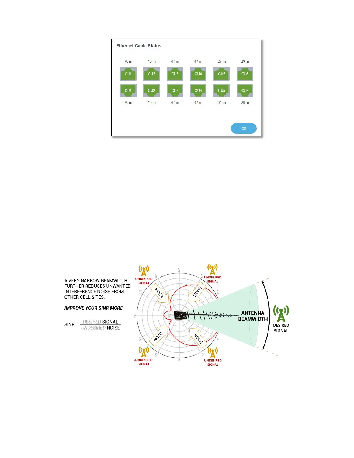
Figure 29: Ethernet Cable Status
Donor Antenna Selection, Placement, and Aiming
Nextivity CEL-FI systems have a major advantage over other system designs, in that each
operator’s channels are independently extracted and processed. This makes it possible to
have a separate donor antenna for each operator, making it possible to aim an operator’s
donor antenna directly at the operator’s cell site.
In this fashion, a donor antenna for a CEL-FI system acts much like a filter, to reject unwanted
interference signals from undesired cell sites or other interference sources. The result is
improved SINR and RSRQ signal quality, which directly translates into more phone signal bars
and faster better cellular service.
Figure 30: Donor Antenna Placement Guidance
Please take your time when carefully selecting the best location to mount the donor antennas.
For a shorter building, the antennas are normally mounted on the top of the building where
they may be pointed in any direction where signals are coming from. For taller buildings, such
as high-rise buildings in metropolitan areas, roof mounted antennas may have poor signal



 To Next Page