General ventilation connection
Ventilation installation must be carried out in accord-
ance with current norms and directives.
To prevent fan noise being transferred to the ventila-
tion devices, it may be a good idea to install a silencer
in the duct. This is especially important if there are
ventilation devices in noise sensitive rooms.
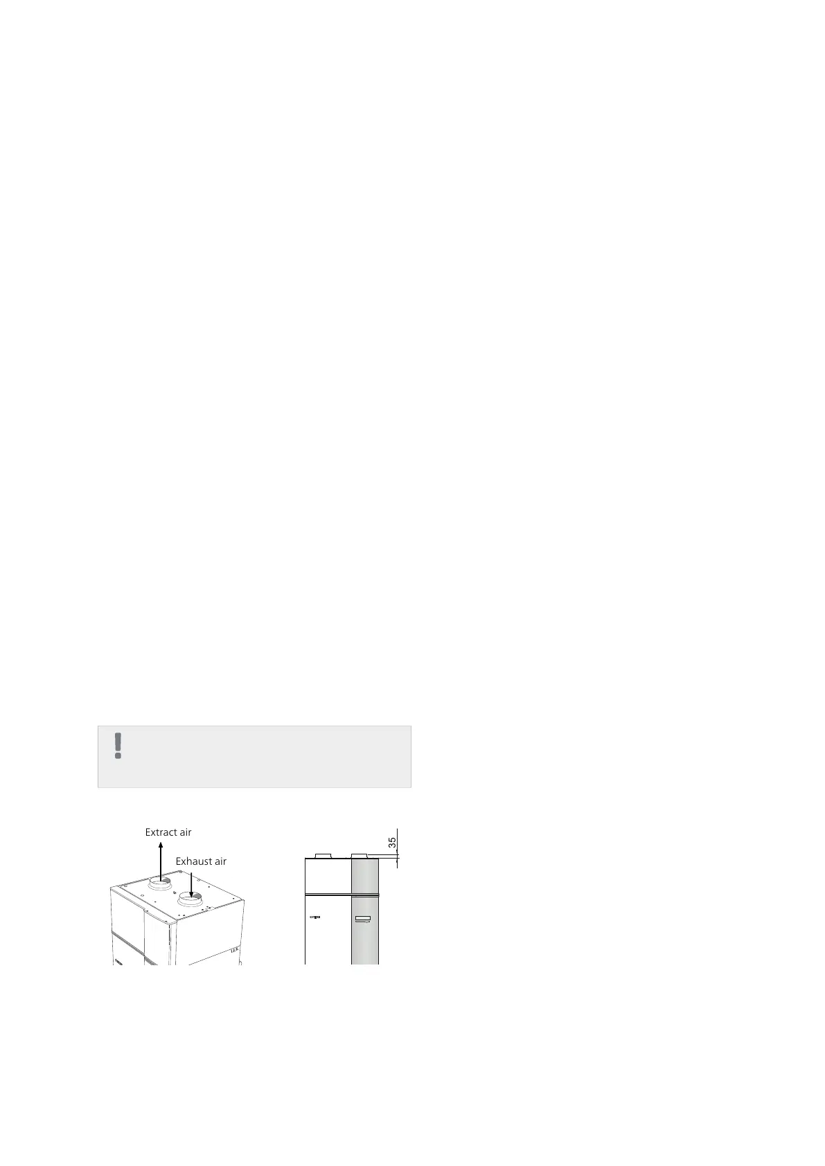
Connections must be made via flexible hoses, which
must be installed so that they are easy to replace. The
extract air duct must be provided with diffusion-tight
insulation (PE30) over its entire length. Ensure that the
condensation insulation is sealed at any joints and/or
at lead-in nipples, silencers, roof cowls or similar. Provi-
sion must be made for inspection and cleaning of the
duct. Make sure that there are no reductions of cross-
sectional area in the form of kinks, tight bends etc.,
since this will reduce the ventilation capacity. The air
duct system must be a minimum of air tightness class
B. The extract air duct must be a maximum of 20 m
long with a maximum of six bends.
Because the heat pump contains the flammable refri-
gerant propane (R290), the air ducting system must be
grounded. This is done by making a good electrical
connection to the ground cables enclosed (2 x) to each
extract air and exhaust air ducts. The cables must then
be connected to the ground studs on top of the top
cover.
Exhaust air duct /kitchen fan
Exhaust air duct (kitchen fan) must not be connected
to F370.
To prevent food vapour being transferred to F370 the
distance between the kitchen fan and the exhaust air
device must be considered. The distance should not be
less than 1.5 m, but this can vary between different
installations.
Always use a kitchen fan when cooking.
NOTE
A duct in a masonry chimney stack must not
be used for extract air.
595
145
440
560 440
2075
25-50
615
35
335
60
120
60
600
200
550
Undvik rördragning
inom markerat område
Ventilation flow
Connect F370 so that all exhaust air except exhaust air
duct air (kitchen fan) passes the evaporator (EP1) in
the heat pump. Lowest ventilation flow must fulfil ap-
plicable standards. For optimum heat pump operation
the ventilation flow must not fall below 28 l/s (100
m³/h) at an exhaust air temperature of at least 20 °C.
At times when the exhaust air temperature is below
20 °C (for example on start up and when there is no
one in the accommodation) the minimum value is 31
l/s (110 m³/h).
The heat pump’s installation area should be ventilated
by at least 5 l/s (18 m³/h). The installation area must
have a volume of at least 8 m³.
Ensure that the ventilation openings are not blocked.
Set the ventilation capacity in the heat pump's menu
system (menu 5.1.5).
Adjusting ventilation
To obtain the necessary air exchange in every room of
the house, the exhaust air devices must be correctly
positioned and adjusted and the fan in the heat pump
adjusted.
Immediately after installation adjust the ventilation so
that it is set according to the projected value of the
house.
A defective ventilation installation may lead to reduced
installation efficiency and thus poorer operating eco-
nomy, and may result in moisture damage to the house.
NIBE™ F370Chapter 4 | Pipe and ventilation connections18

 Loading...


