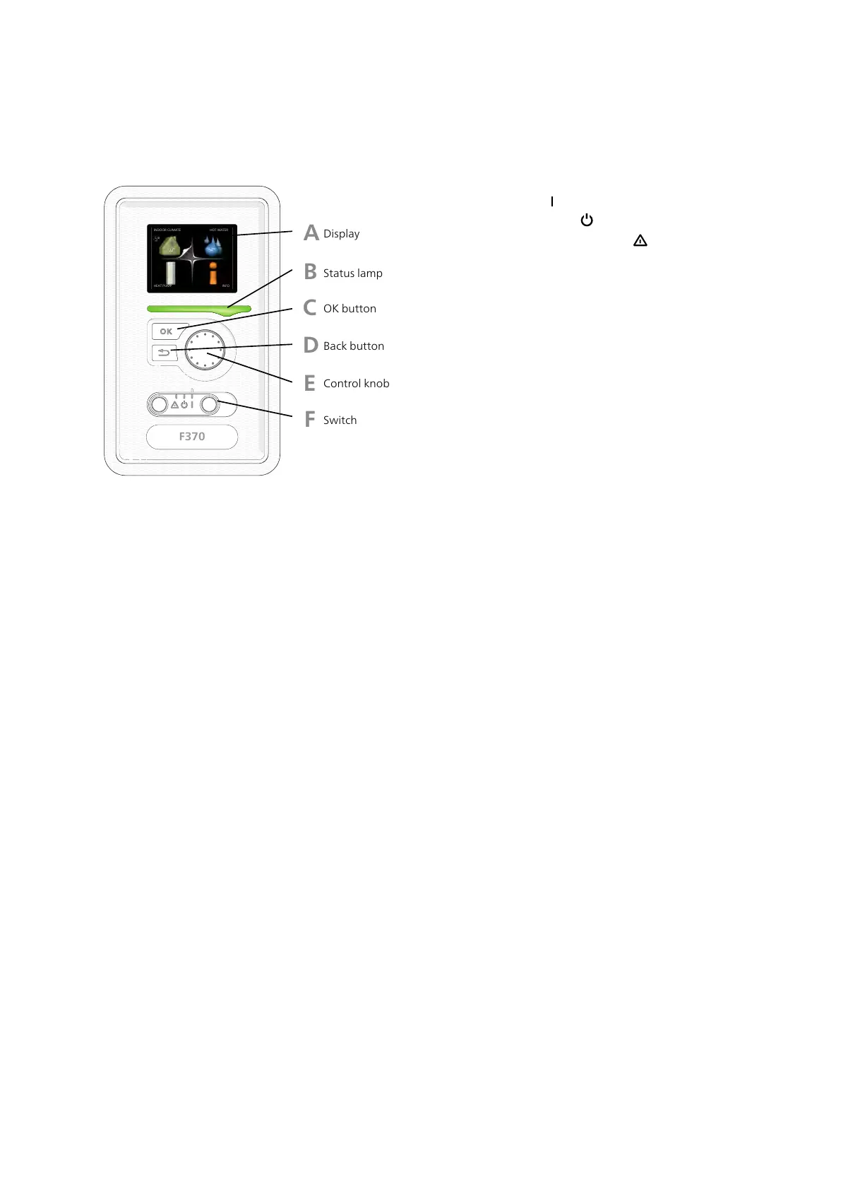
Display unit
A
B
C
D
E
F
Display
Status lamp
OK button
Back button
Control knob
Switch
INDOOR CLIMATE
HEAT PUMP INFO
HOT WATER
Display
Instructions, settings and operational informa-
tion are shown on the display. The easy-to-read
display and menu system, facilitates navigation
between the different menus and options to
set the comfort or obtain the information you
require.
A
Status lamp
The status lamp indicates the status of the heat
pump. It:
■
lights green during normal operation.
■
lights yellow in emergency mode.
■
lights red in the event of a deployed alarm.
B
OK button
The OK button is used to:
■
confirm selections of sub menus/options/set
values/page in the start guide.
C
Back button
The back button is used to:
■
go back to the previous menu.
■
change a setting that has not been con-
firmed.
D
Control knob
The control knob can be turned to the right or
left. You can:
■
scroll in menus and between options.
■
increase and decrease the values.
■
change page in multiple page instructions
(for example help text and service info).
E
Switch (SF1)
The switch assumes three positions:
■
On ()
■
Standby ( )
■
Emergency mode ( ) (see page 56)
Emergency mode must only be used in the
event of a fault on the heat pump. In this mode,
the compressor switches off and the immersion
heater engages. The heat pump display is not
illuminated and the status lamp illuminates
yellow.
F
USB port
The USB port is hidden beneath the plastic
badge with the product name on it.
The USB port is used to update the software.
Visit http://www.nibeuplink.com and click the
"Software" tab to download the latest software
for your installation.
G
NIBE™ F370Chapter 7 | Control - Introduction34
7 Control - Introduction

 Loading...


