Service actions
NOTE
Servicing should only be carried out by persons
with the necessary expertise.
When replacing components on F370 only
replacement parts from NIBE may be used.
Emergency mode
Emergency mode is used in event of operational inter-
ference and in conjunction with service.
Emergency mode is activated by setting switch (SF1)
in mode " ". This means that:
■
The status lamp illuminates yellow.
■
The display is not lit and the control computer is not
connected.
■
The temperature in the heat pump boiler section is
controlled by a fixed thermostat (BT30) on 63 °C.
■
The compressor is off and only the fan, heating me-
dium pump and the electric additional heat are act-
ive. The additional heat power in emergency mode
is set in the immersion heater card (AA1). See page
25 for instructions.
■
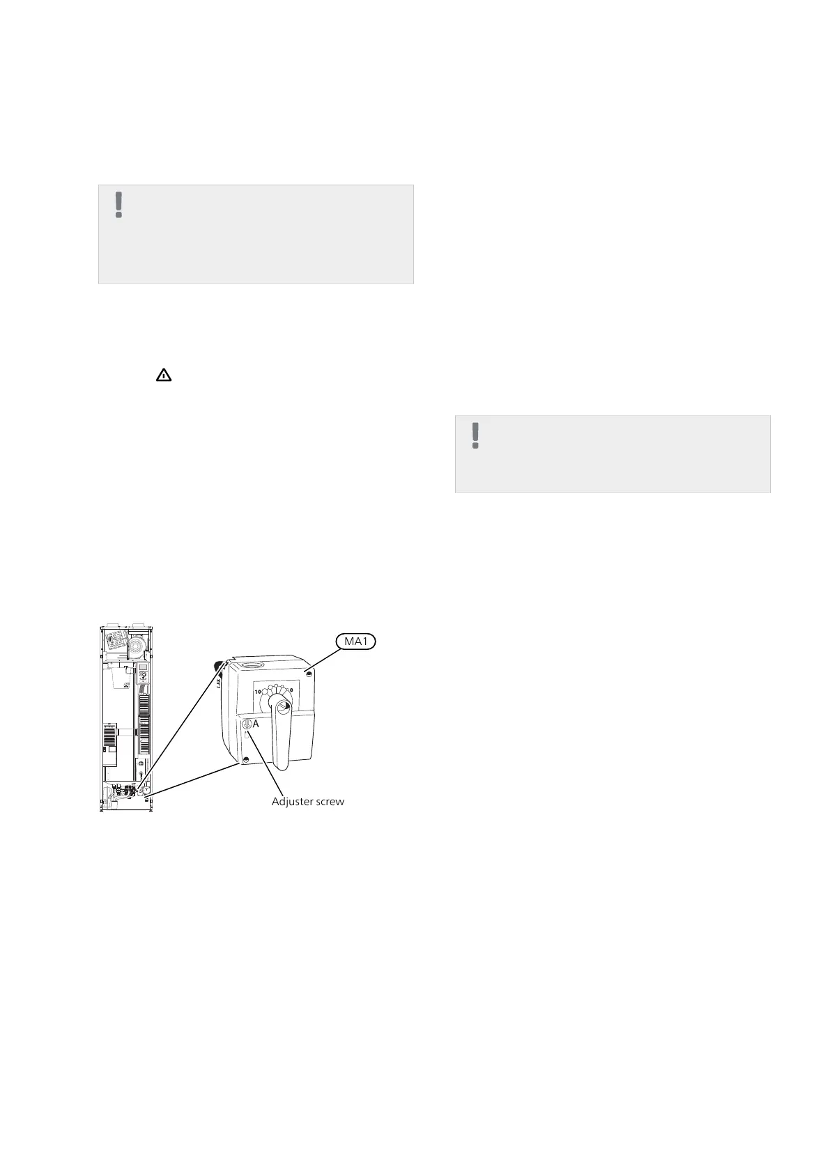
The automatic heating control system is not opera-
tional, so manual shunt operation is required. This is
done by turning the adjustment screw on the shunt
motor (MA1to "manual mode" and then turning the
shunt lever to the desired position.
Draining the water heater
The water heater can be drained via the safety valve
(FL1) or via the overflow cup (WM1).
1.
Disconnect the overflow pipe from the safety valve
(FL1) and connect a hose to a draining pump in-
stead. Where no draining pump is available, the
water can be released into the overflow cup
(WM1).
2.
Open the safety valve (FL1).
3.
Open a hot water tap to let air into the system. If
this is not sufficient, detach the pipe connection
(XL4) on the hot water side to see if air is entering.
Draining the climate system
In order to carry out service on the climate system, it
may be easier to drain the system first.
NOTE
There may be some hot water when draining
the heating medium side/climate system.
There is a risk of scalding.
The hot water can be tapped through safety valve (FL2)
via the overflow cup (WM1) or through a hose that is
connected to the safety valve's (FL2) or the drain valve's
(XL10) outlet.
1.
Open the safety valve (FL2) or the drain valve
(XL10).
2.
Set the vent valve for the climate system (QM20)
in the open position for air supply.
NIBE™ F370Chapter 9 | Service56
9 Service

 Loading...


