Connections
NOTE
To prevent interference, unscreened commu-
nication and/or sensor cables to external con-
nections must not be laid closer than 20 cm
from high voltage cables.
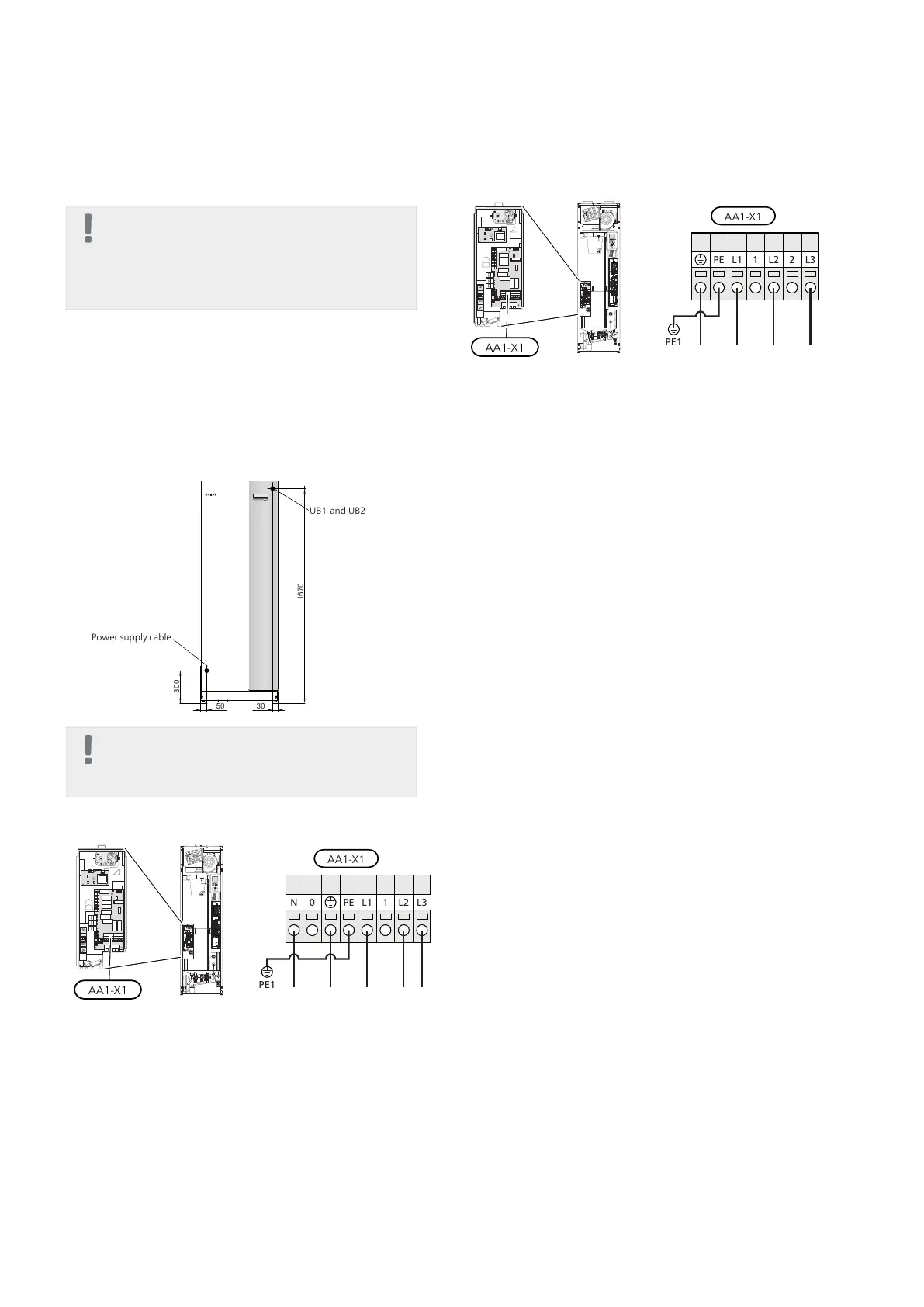
Power connection
F370 must be installed via an isolator switch with a
minimum breaking gap of 3mm. Minimum cable area
must be sized according to the fuse rating used. Sup-
plied cable (length approx. 2 m) for incoming supply
electricity is connected to terminal block X1 on the
immersion heater board (AA1). The connection cable
can be found on the back of F370 (see dimensions
diagram below).
Power supply cable
UB1 and UB2
NOTE
F370 is not switchable between 3x230V and
3x400V.
Connection 3x400V
Connection 3x230V
If separate supply to the compressor and immersion
heater is required, see section "Possible selection for
AUX inputs" on page 26.
Tariff control
If the voltage to the immersion heater and/or the
compressor disappears for a certain period, there must
also be blocking via the AUX-input at the same time,
see "Possible selection for AUX inputs".
21Chapter 5 | Electrical connectionsNIBE™ F370

 Loading...


