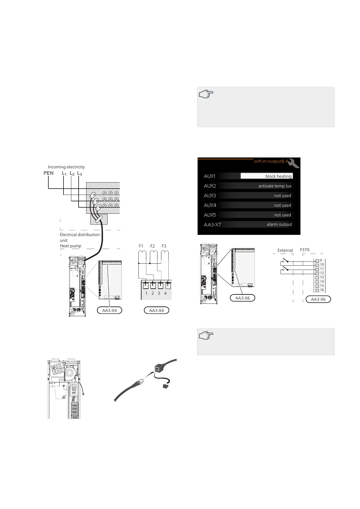
Connecting current sensors
A current sensor should be installed on each incoming
phase conductor in to the distribution box to measure
the current. The distribution box is an appropriate in-
stallation point.
Connect the current sensors to a multi-core cable in an
enclosure next to the electrical distribution unit. The
multi-core cable between the enclosure and the heat
pump must have a cable area of at least 0.5 mm².
Connect the cable to the input board (AA3) on terminal
X4:1-4 block - where X4:1 is the common terminal block
for the three current sensors.
The size of the property's main fuse is set in menu
5.1.12.
AA3-X4 AA3-X4
Electrical distribution
unit
Heat pump
Incoming electricity
1 2 3 4
-T1 -T2 -T3
NIBE Uplink™
Connect the network connected cable (straight, Cat.5e
UTP) with RJ45-contact (male) to RJ45 contact (female)
on the rear of the heat pump.
External connection options
F370 has software controlled inputs and outputs on
the input card (AA3), for connecting the external switch
function or sensor. This means that when an external
switch function or sensor is connected to one of six
special connections, the correct function must be selec-
ted to the correct connection in the software in F370.
Caution
If an external switch function or sensor is con-
nected to F370, the function to use input or
output must be selected in menu 5.4, see page
54.
Selectable inputs on the input card for these functions
are AUX1 (X6:9-10), AUX2 (X6:11-12), AUX3 (X6:13-
14), AUX4 (X6:15-16) and AUX5 (X6:17-18). Selectable
outputs are AA3:X7.
block heating
activate temp lux
not used
not used
not used
alarm output
soft in/outputs5.4
F1245Externt
9
10
11
12
13
14
15
1
6
B
A
The example above uses the inputs AUX1 (X6:9-10) andAUX2
(X6:11-12) on the input circuit board (AA3).
Caution
Some of the following functions can also be
activated and scheduled via menu settings.
Possible selection for AUX inputs
Switch for external blocking of addition and/or
compressor
Blocking for addition heat and compressor is connected
on two different AUX inputs.
If external blocking of additional heat and/or com-
pressor is wanted, this can be connected to terminal
block X6 on the input board (AA3), which is positioned
behind the front cover.
The additional heat and/or the compressor are discon-
nected by connecting a potential-free switch function
to the input selected in menu 5.4, see page 54.
External blocking of addition and compressor can be
combined.
NIBE™ F370Chapter 5 | Electrical connections26

 Loading...


