General
All electrical equipment, except the outdoor sensors,
room sensors and the current sensors are ready connec-
ted at the factory.
■ Disconnect the heat pump before insulation testing
the house wiring.
■ F370 is not switchable between 3x230V and 3x400V.
■ If the building is equipped with an earth-fault
breaker, F370 should be equipped with a separate
one.
■ If a miniature circuit breaker is used it should have
at least motor characteristic “C”. See page 64 for
fuse size.
■ For the heat pump wiring diagram, see page 70.
■ Communication and sensor cables to external con-
nections must not be laid close to high current cables.
■ The minimum area of communication and sensor
cables to external connections must be 0.5 mm² up
to 50 m, for example EKKX or LiYY or equivalent.
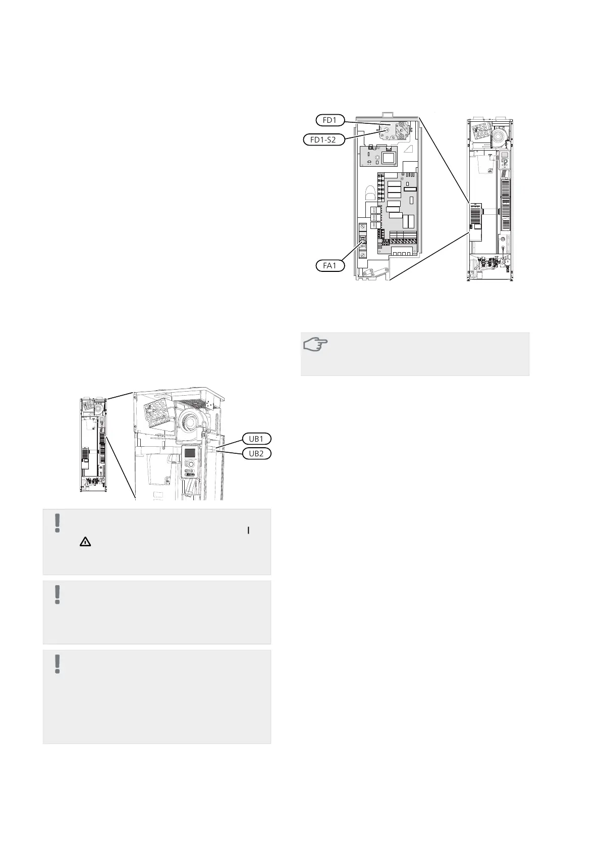
■ When cable routing in F370, cable grommets UB1and
UB2, (marked in image) must be used. In UB1 and
UB2 the cables are inserted through the heat pump
from the back to the front. For dimensions diagram
see page 21.
NOTE
The switch (SF1) must not be moved to "" or
" " until the boiler has been filled with water.
Otherwise the temperature limiter, thermostat
and the immersion heater can be damaged.
NOTE
If the supply cable is damaged, only NIBE, its
service representative or similar authorised
person may replace it to prevent any danger
and damage.
NOTE
Electrical installation and service must be car-
ried out under the supervision of a qualified
electrician. Cut the current with the circuit
breaker before carrying out any servicing.
Electrical installation and wiring must be car-
ried out in accordance with the stipulations in
force.
Miniature circuit breaker (FA1)
Control (230 V), fan, compressor, circulation pump etc.
are internally fused by a miniature circuit breaker (FA1).
Caution
Check the miniature circuit-breaker (FA1). It
may have tripped during transportation.
Temperature limiter (FD1)
The temperature limiter (FD1) cuts the current supply
to the electric additional heat if the temperature rises
between 90 and 100°C and can be manually reset.
Resetting
The temperature limiter (FD1) is accessible behind the
front cover. Reset the temperature limiter by carefully
pressing the button (FD1-SF2) using a small screwdriver.
19Chapter 5 | Electrical connectionsNIBE™ F370
5 Electrical connections

 Loading...


