"temporary lux" is activated for the time that the con-
tact is connected.
Contact for activation of “external adjustment"
An external contact function can be connected to F370
to change the supply temperature and the room tem-
perature.
When the switch is closed the temperature changes in
°C (if the room sensor is connected and activated). If a
room sensor is not connected or activated, the desired
change of "temperature" (heating curve offset) with
the number of steps selected is set. The value is ad-
justable between -10 and +10.
■
climate system 1
The switch must be potential-free and connected to
the selected input (menu 5.4, see page 54) on termin-
al block X6 on the input board (AA3).
The value for the change is set in menu 1.9.2, "extern-
al adjustment".
■
climate system 2 to 4
External adjustment for climate systems 2 to 4 re-
quires accessory (ECS 40 or ECS 41).
See the accessory’s installer handbook for installation
instructions.
Contact for activation of fan speed
An external contact function can be connected to F370
for activation of one of the four fan speeds. The switch
must be potential free and connected to the selected
input (menu 5.4, see page 54) on terminal block X6 on
the input circuit board (AA3). When the switch closes,
the selected fan speed is activated. Normal speed is
resumed when the contact is opened again.
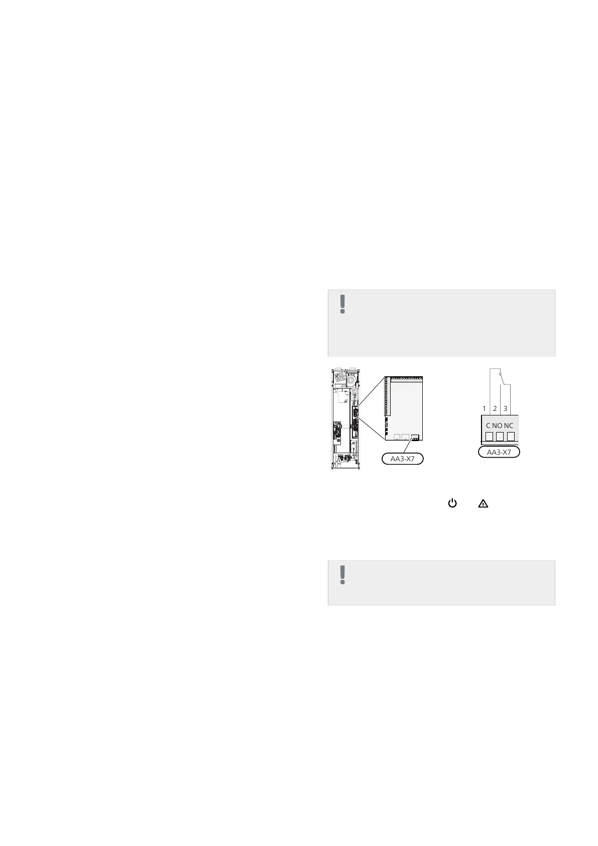
Possible selection for AUX output (potential
free variable relay)
It is possible to have an external connection through
the relay function via a potential free variable relay
(max 2 A) on the input circuit board (AA3), terminal
block X7.
Optional functions for external connection:
■
Indication of buzzer alarm.
■
Control of circulation pump for hot water circulation.
■
External circulation pump, for example external pump
and shunt group.
If any of the above is installed to terminal block X7 it
must be selected in menu 5.4, see page 54.
The common alarm is preselected at the factory.
NOTE
An accessory card is required if several func-
tions are connected to terminal block X7 at
the same time that the buzzer alarm is activ-
ated (see page 62).
The picture shows the relay in the alarm position.
When switch (SF1) is in the " " or “ ” position the
relay is in the alarm position.
External circulation pump or hot water circulation
pump connected to the buzzer alarm relay as illustrated
below.
NOTE
Mark up any junction boxes with warnings for
external voltage.
NIBE™ F370Chapter 5 | Electrical connections28

 Loading...


