Electrical connection
23
FIGHTER 1240
Install the outside temperature sensor in the shade on
a wall facing north or north-west, so it is unaffected by
the morning sun. The sensor is connected to terminals
X1:1 and X1:2 on the EBV-card (2). Use a two-wire
cable of at least 0.5 mm
2
.
If the outside temperature sensor cable runs close to
power cables, screened cable should be used.
All conduits should be sealed to avoid condensation in
the sensor capsule.
Alarm
A common alarm is given in the following instances:
High pressure switch (HP) has tripped. Indicated as
HP alarm.
LP pressure switch (LP) has tripped. Indicated as an
LP alarm.
The motor cut-out (MP) has tripped, indicated by an
MP alarm.
Pressure/level monitor brine (accessory) indicated as
pressure/level brine.
Brine temp. low, indicates a low brine temperature. Not
indicated when menu 5.2 is set to automatic return On.
Flow sensor fault is indicated by a Sensor alarm.
Hot water sensor fault is indicated by a Sensor alarm.
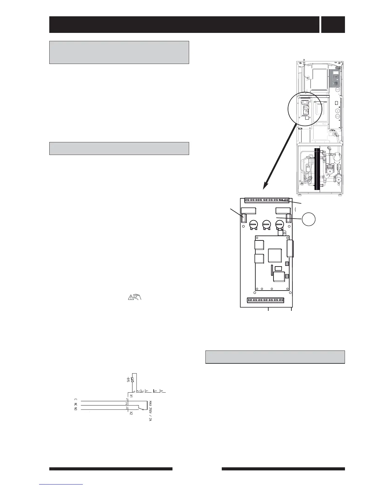
External indication of common alarms is possible
through the relay function on the load monitor card (2),
terminals X2:1—3.
The picture shows the relay in the alarm position.
When switch (8) is in the 0 or “ ” position the
relay is in the alarm position.
Alarm/alarm outputs
Connecting the
outside temperature sensor
Outdoor temperature sensor
Alarm output,
common
alarm
FIGHTER 1240 is equipped with a soft-start relay (97),
which limits the inrush current, see section Technical
specifications.
The compressor must not be forced to start with peri-
ods shorter that 1 start per 15 minutes.
Soft-start relay*
*Applies to 3 x 400 V and 1 x 230 V -8 and -12
X2