Electrical connection16
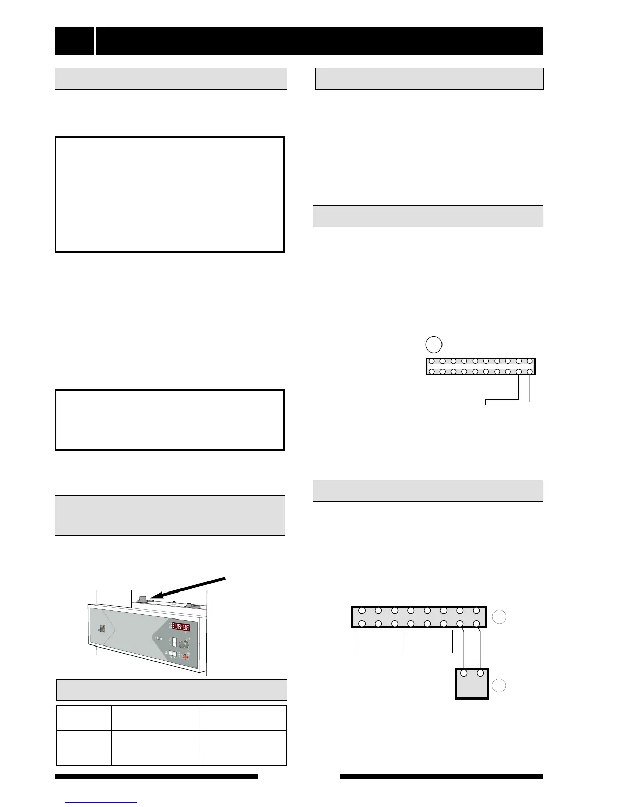
Install the outside sensor in the shade on a wall facing
north or north-west, so it is unaffected by the morning
sun. The sensor is connected with two-wire cable to
terminal (14) positions “7” and “8”.
All conduits should be sealed to avoid condensation in
the sensor capsule.
Connecting the outside sensor
Output Max load Group fuse
(kW) phase (A) (A)
6.0 12.8 16
8.0 14.9 16
9.0 19.2 20
All electrical equipment except for the outdoor sensor
has been connected at the factory. Disconnect the
heat pump before insulation testing the house wiring.
The immersion heater of 9 kW is fitted in the boiler
section, and on delivery is connected for an output of
9.0 kW.
Reconnection between the different outputs is done
by opening the cover on the distribution box see the
section Service - Opening the cover on the distribu-
tion box, and moving specific cables as set out in the
instructions in the section Wiring diagram - Changing
the output.
FIGHTER 600P
For the Installer
Connection Output as set at the factory
Max phase current
NOTE!
Reset the temperature limiter,
it may have tripped during transport.
NOTE!
The switch (8) must not be moved
from “0” until the boiler has been
filled with water Otherwise the
temperature limiter, thermostat,
compressor and the immersion heater
can be damaged.
The automatic heating control system, circulation
pump (16), compressor and its cabling, are internally
fuse protected with a miniature circuit breaker (7).
The temperature limiter (6) is accessible behind the
upper service cover, see the figure.
The temperature limiter is reset by firmly pressing in
the rubber membrane.
Resetting the
temperature limiter
The supply to the heat pump is connected to termi-
nal (9) via a strain relief. Connection must not be car-
ried out without the permission of the electricity suppli-
er and under the supervision of a qualified electrician.
The cable entry conduit is dimensioned for cable with
a max Ø 19 mm. The power is controlled via a contac-
tor which is operated by a microprocessor.
The temperature limiter (6) cuts off the supply to the
immersion heater if the temperature rises to between
90 and 100 °C; it can be manually reset by pressing
the button on the temperature limiter.