Electrical circuit diagram 25
FIGHTER 600P
For the Installer
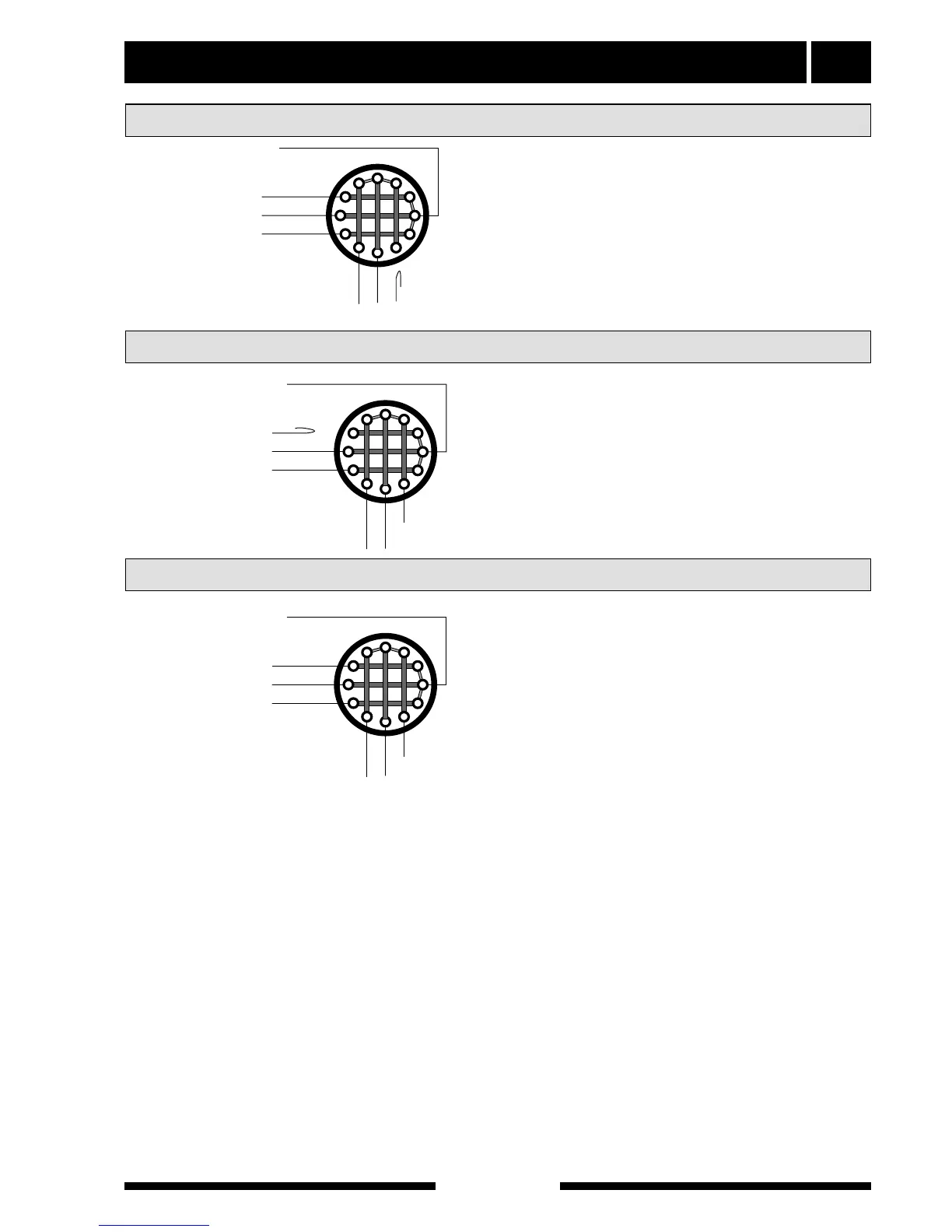
3 x 1 kW White
3 x 1 kW White
2 x 1 kW White
The brown cable from terminal “22” on the relay card
is disconnected from the immersion heater.
The white cable from terminal 6 on the connector is
disconnected from the immersion heater.
NOTE! In this output step only 2 kW is obtained in
standby mode.