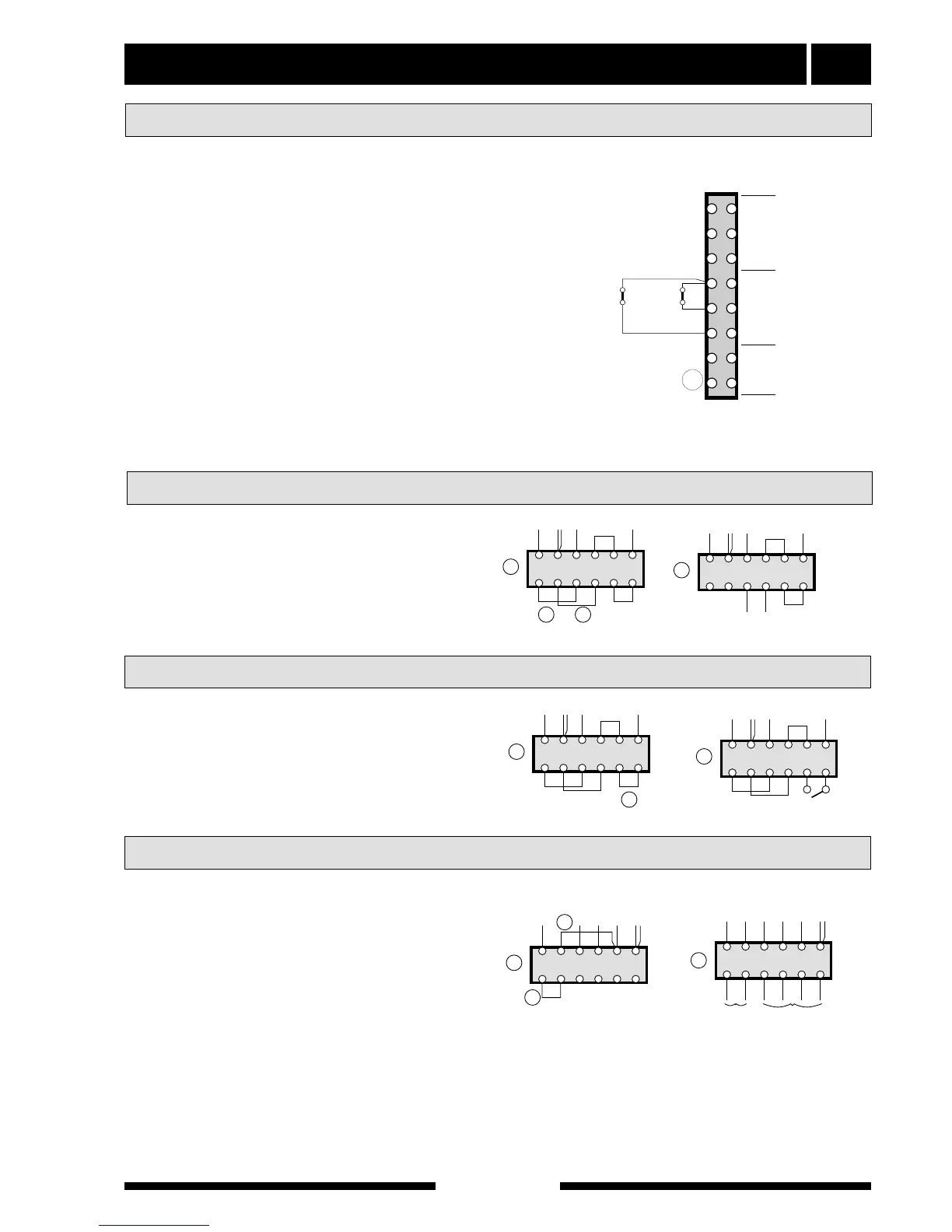
A timer for night tariff or a room thermostat ( first
remove the strap) can be connected to positions (4)
and (6) on terminal (14). The timer or the room ther-
mostat must have a potential free contact and have a
design where the circuit opens when a lower tempera-
ture is required.
The microprocessor in FIGHTER 600P corrects the
originally selected setting for Heating curve offset by
three steps downwards.
An external switch that switches off the circulation
pump can be connected (first remove the strap) at
positions (4) and (5) on terminal (14). For example, a
thermostat can be connected that detects the flow
temperature and switches off the circulation pump, if
the flow temperature becomes too high. The switch or
thermostat must have a potential free contact and
have a design where the circuit opens when the circu-
lation pump should be switched off.
Electrical connection 17
FIGHTER 600P
For the Installer
The heat pump’s compressor can - if you wish - also be
controlled by an external switch by replacing strap C on
terminal (12) with a potential free switch function (230
V~, 6A, motor operation).
NOTE! In this position some parts of the electrical sys-
tem are live, even when the power switch (8) is set to
“0”.
The heat pump’s compressor can be externally fed if so
required by removing the straps A and B from terminal
(12). The separate voltage supply (230 V~, 6A, motor
operation) is connected to “3” and “4”.
NOTE! In this position some parts of the electrical sys-
tem are live, even when the power switch (8) is set to
“0”.
Separate feed between the immersion heater and
remainder can be obtained by making the following
reconnections on terminal (9):
■ Remove straps D and E.
■ Move the cable between terminal 13, pos “N”, and
the relay card, pos “9”, from terminal 13 to terminal
9, pos “1B”.
■ The immersion heater is now fed via terminal 9,
pos “N-L1-L2-L3” and the remainder (compressor,
circulation pump, fan and control) are fed via termi-
nal 9, pos “1A-1B”.