Commissioning and adjusting18
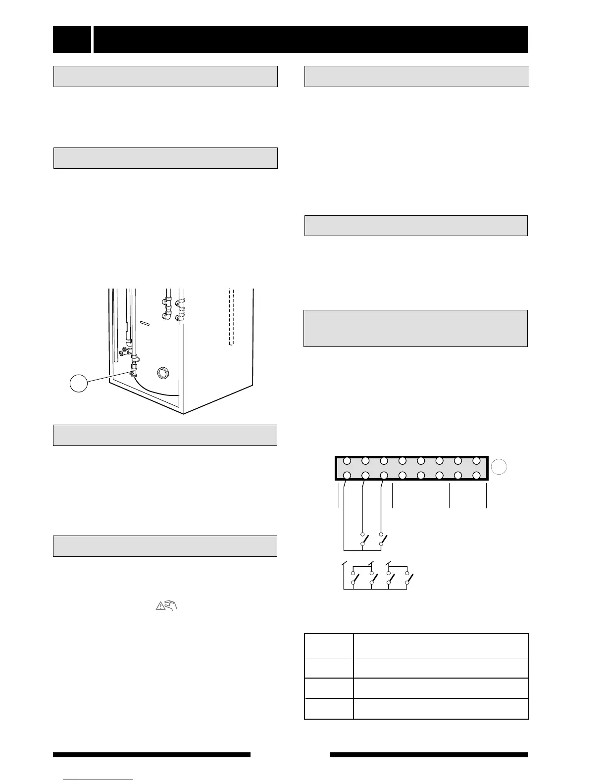
The heating system is drained through the drain valve
(51). This is located behind the lower service cover.
The service cover is opened by loosening both
screws on the upper edge of the cover and then lift
the cover up/forward.
For the Installer
FIGHTER 600P
NOTE! As an option to the procedure set out below a
drying process can be used, see the Drying process
section.
■ Set the switch (8) to “”. In this mode the elec-
tronics are disconnected, so the display window is
not lit. The thermostat (3) opens at 71 °C in this
mode.
■ When the room temperature goes above 16 °C set
switch (8) to “1”. NOTE! The compressor has a
start delay of about 20 minutes.
■ Set the design capacity on the circulation pump
using its switch (35). See the section Pipe connec-
tions - Pump and pressure drop diagram. Make
sure that the switch is not in an intermediate posi-
tion.
■ Remove the upper service cover so the pressure
gauge (42) becomes visible
■ Connect a hose to the filling valve (49) and open
the valve to fill the boiler and the radiator system.
■ After a while the pressure gauge (42) will show ris-
ing pressure. When the pressure has reached
about 2.5 bar a mix of air and water starts to
emerge from the safety valve (52). Close the filling
valve (49).
Check that the switch (8) is set to “0”.
Check that valves (44) and (50) are fully open and that
the temperature limiter (6) has not tripped (press the
firmly on the rubber membrane).
Filling the heating system
Starting
Preparations
■ Vent the electric boiler through the safety valve
(52), venting screws (17), (59) and the rest of the
heating system through the relevant venting
valves.
■ Keep topping up and venting until all air has been
removed and the pressure is correct.
Venting the heating system
Air is initially released from the hot water and venting
may be necessary. If bubbling sounds can be heard
from the heat pump, the entire system requires further
venting. NOTE! Safety valve (52) also acts as a man-
ual venting valve. Operate it with care, since it opens
quickly. When the system is stable (correct pressure
and all air eliminated) the automatic heating control
system can be set as required. See the section Room
temperature - Setting the Automatic heating control
system and Front panel.
Readjustment
Draining the heating system
The output steps of the immersion heater can be dis-
connected by means of a load sensor or a centralised
load control relay. This is done with making contacts,
connected to terminal (14).
If both the load monitor and centralised load control
are to be used these are connected in parallel.
Centralised load control and
load monitor
Rundstyrning
eller effektvakt
14
123 4 5678
U-PUMPE PARALLEL +–––AB
SCHUTZKLEINSPANNUNG SELV
AB
FERNSTEUERUNGRUNDSTEUERUNG AUSSENFÜHLER
Rundstyrning (RS)
och effektvakt (BV)
RSBV RSBV
The table below describes output disabling:
External Disconnected output step
contact when the contact is made
5 and 6
(max electrical output 6 kW with standard connection)
4, 5, and 6
(max electrical output 3 kW with standard connection)
3, 4, 5 and 6
(no electrical output available)
A
B
A and B