Room temperature
7
FIGHTER 600P
For Home Owners
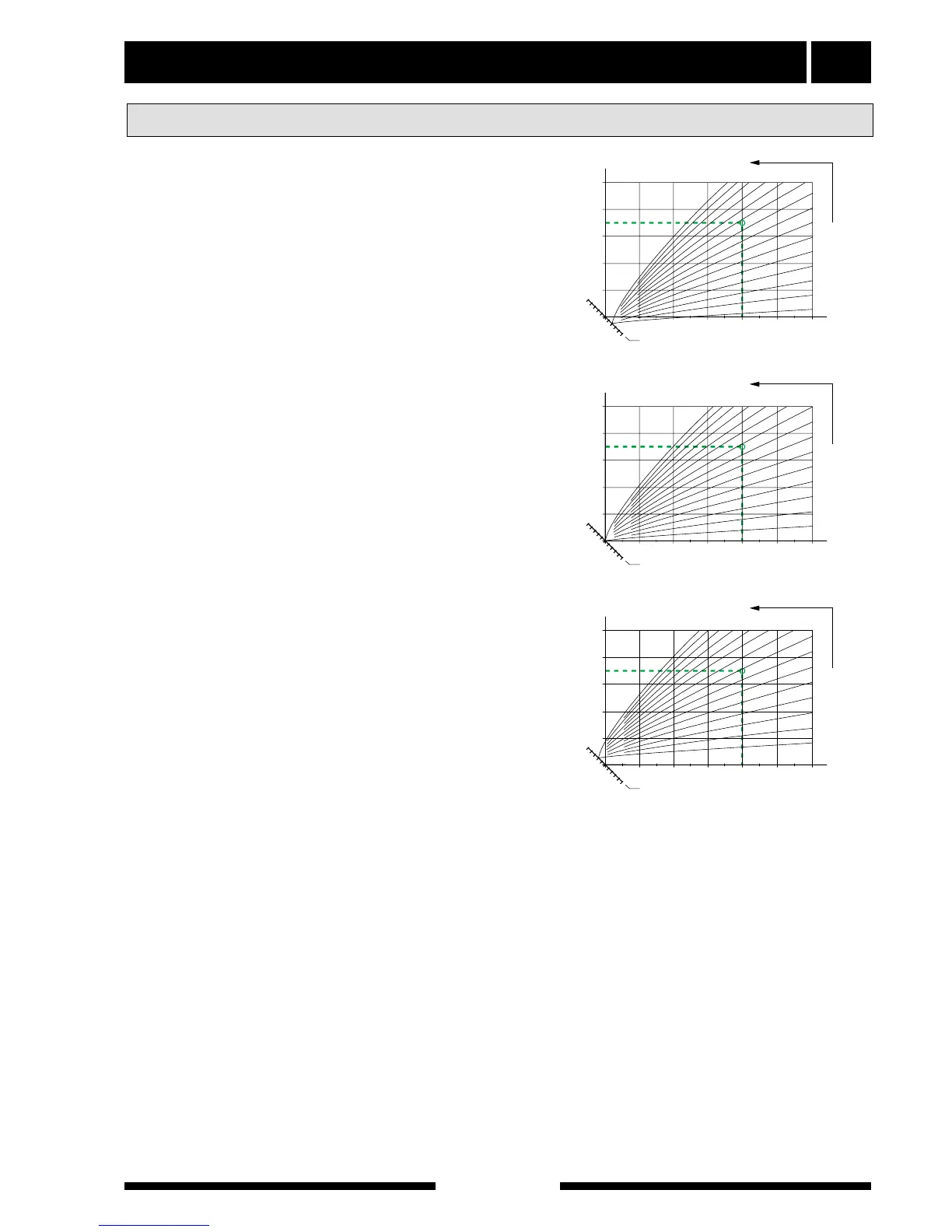
The association between the outdoor temperature and
the flow temperature is set using the Heating curve
selection (37) and Increase/reduce heat buttons (38).
The design flow temperature and the design outdoor
temperature are used as the input data in the adjoin-
ing diagrams to read the curve slope, which is set
using the Heating curve selection knob.
The setting on the Increase/reduce heat knob deter-
mines at which outdoor temperature heating should
stop. If the offset is set to 0 this means heating stops
at the outdoor temperature of + 20 °C. As you normal-
ly have a degree of free heating a value below zero
can be set with this knob.
The adjoining diagram shows the curve intersections
at offsets - 2, ± 0 and + 2. The default setting from the
factory is curve 10 on Heating curve selection and off-
set - 2 on Increase/reduce heat.
In those cases where the heating system’s design flow
temperature is not known the map below can be used
as a guide for setting Heating curve selection.
The first figure applies to a radiator system and the fig-
ure in brackets applies to floor heating installed in a
concrete floor structure where the max flow tempera-
ture is 35 °C. When the floor heating system is
installed in a wooden floor structure you can start with
the figure before brackets and reduce this value by
two units.
A suitable setting on the Increase/reduce knob is - 2
for radiator systems and -1 for floor heating.
Basic values for the automatic heating control system