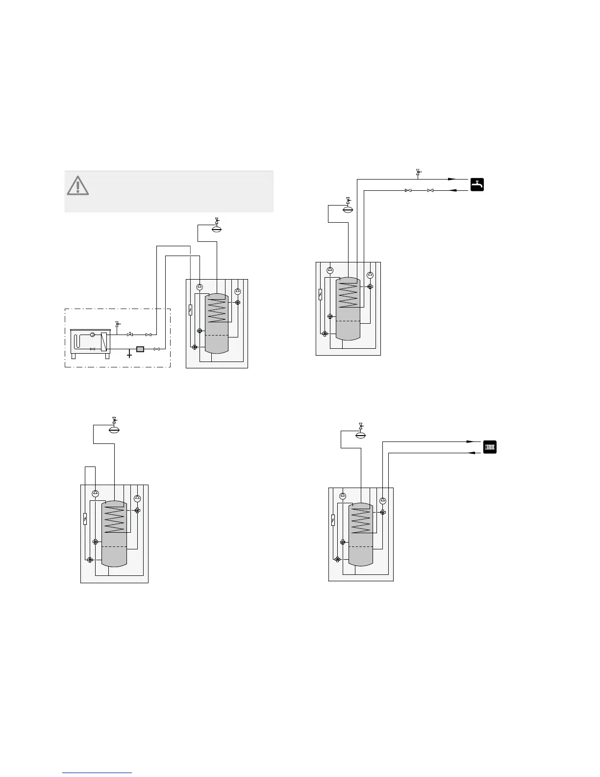
Connecting to heat pump
All outdoor pipes must be thermally insulated with at
least 20mm thick pipe insulation.
VVM 310 is not equipped with shut off valves; these
must be installed outside the indoor module to facilit-
ate any future servicing.
NOTE
The charge circuit is supplied with trim valve
for basic setting of the charge flow.
-FL2
-CM1
-EB15
-XL8
-XL9
-RN10
-EB101
XL2
XL1
-HQ1
-QM1
-QM41
-FL10
-QM40
-EB101
Connection as electric boiler
Connect the pipe for docking in from the heat pump
(XL8) with the pipe out to the heat pump (XL9).
-FL2
-CM1
-EB15
-XL8 -XL9
Connecting cold and hot water
The mixing valve must be installed if the factory setting
is changed so that the temperature can exceed 60 °C.
If the factory setting is changed, national regulations
must be observed. The setting is made in menu 5.1.1
(See page 51).
-FL2
-XL4
-XL3
-CM1
-EB15
-FL1
-QM40-RM1
Connecting the climate system
When connecting to a system with thermostats on all
radiators/underfloor heating coils, a relief valve must
be fitted, or a thermostat must be removed to ensure
sufficient flow.
-FL2
-CM1
-EB15
-XL1
-XL2
15Chapter 4 | Pipe connectionsNIBE™ VVM 310