Optional connections
Load monitor
When many power consumers are connected in the
property at the same time as the electric addition is
operating, there is a risk of the property's main fuse
tripping. The electric boiler has integrated load monit-
ors that control the electrical steps for the electrical
addition by redistributing the power between the dif-
ferent phases or disengaging in event of overload in a
phase. Reconnection occurs when other current con-
sumption is reduced.
Connecting current sensors
A current sensor should be installed on each incoming
phase conductor in to the distribution box to measure
the current. The distribution box is an appropriate in-
stallation point.
Connect the current sensors to a multi-core cable in an
enclosure next to the distribution box. Use a multi-core
cable of at least 0.5 mm2 from the enclosure to the
indoor module.
Connect the cable to the input card (AA3) on terminal
block X4:1-4 where X4:1 is the common terminal block
for the three current sensors.
The size of the property’s main fuse is set in menu
5.1.12.
Inkommande el
LPEN
1
L
2
L
3
Elcentral
Värmepump
AA3-X4 AA3-X4
Electrical
distribution unit
VVM 310
Incoming electricity
1234
-T1
VVM 310
-T2 -T3
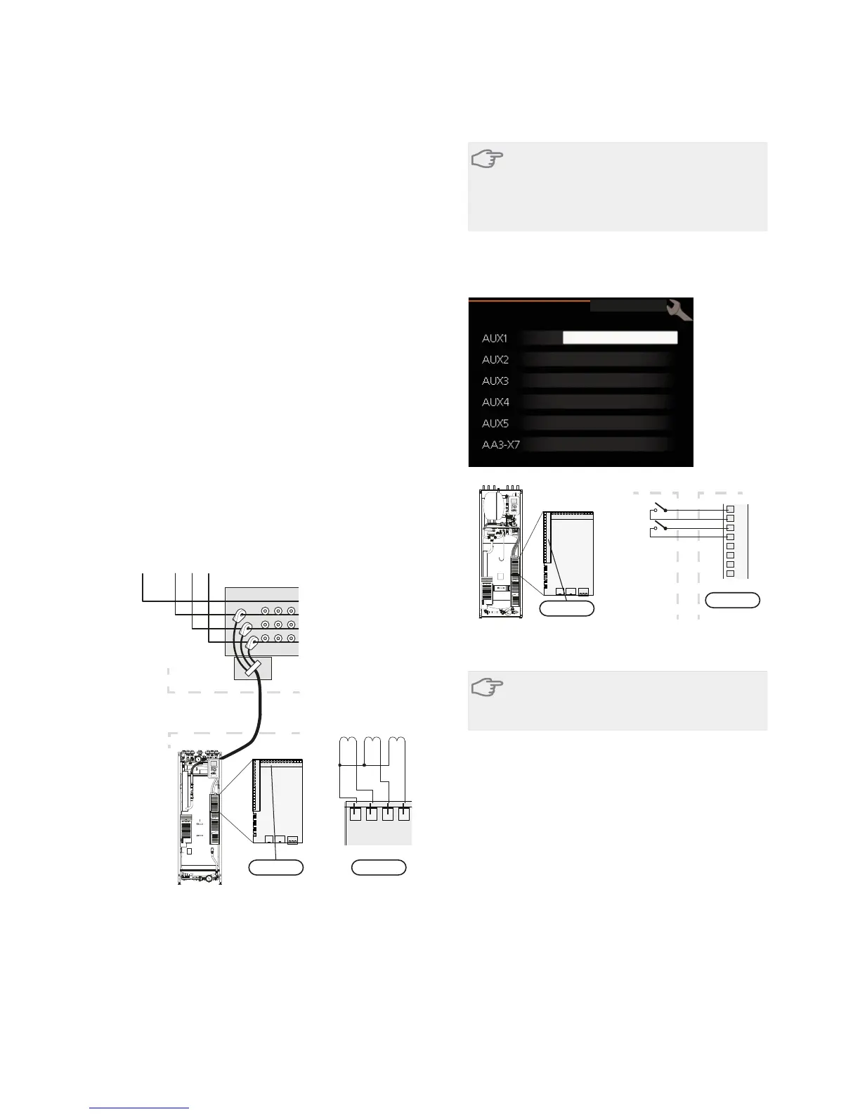
External connection options
VVM 310 has software controlled inputs and outputs
on the input card (AA3), for connecting the extern
switch function or sensor. This means that when an
external switch function or sensor is connected to one
of six special connections, the correct function must be
selected to the correct connection in the software in
VVM 310.
Caution
If an external switch function or sensor is con-
nected to VVM 310, the function to use input
or output must be selected in menu 5.4, see
page 53.
Selectable inputs on the input card for these functions
are AUX1 (X6:9-10), AUX2 (X6:11-12), AUX3 (X6:13-
14), AUX4 (X6:15-16) and AUX5 (X6:17-18). Selectable
outputs are AA3:X7.
EORFN KHDWLQJ
DFWLYDWH WHPS OX[
QRW XVHG
QRW XVHG
QRW XVHG
DODUP RXWSXW
VRIW LQRXWSXWV
9
10
11
12
13
14
15
16
B
A
$$;
([WHUQDO 990
AA3-X6
VVM320
The example above uses the inputs AUX1 (X6:9-10) andAUX2
(X6:11-12) on the input circuit board (AA3).
Caution
Some of the following functions can also be
activated and scheduled via menu settings.
Possible selection for AUX inputs
Switch for external blocking of addition and/or
compressor
In those cases external blocking of addition and/or
compressor is wanted, this can be connected to termin-
al block X6 on the input card (AA3), which is positioned
behind the front cover.
The additional heat and/or the compressor are discon-
nected by connecting a potential free switch function
to the input selected in menu 5.4, see page 53.
External blocking of addition and compressor can be
combined.
A closed contact results in the electrical output being
disconnected.
Contact for external tariff blocking
In those cases external blocking of heat is used, this
can be connected to terminal block X6 on the input
card (AA3), which is positioned behind the front cover.
NIBE™ VVM 310Chapter 5 | Electrical connections26