Heating operation is disconnected by connecting a
potential free switch function to the input selected in
menu 5.4, see page 53.
A closed switch results in blocked heating operation.
Contact for activation of “temporary lux"
An external contact function can be connected to VVM
310 for activation of the hot water function“temporary
lux". The switch must be potential free and connected
to the selected input (menu 5.4, see page 53) on ter-
minal block X6 on the input circuit board (AA3).
"temporary lux" is activated for the time that the con-
tact is connected.
Contact for activation of “external adjustment"
An external contact function can be connected to VVM
310 to change the supply temperature and the room
temperature.
When the switch is closed the temperature changes in
°C (if the room sensor is connected and activated). If a
room sensor is not connected or not activated, the de-
sired offset of "temperature" (heating curve offset) is
set with the number of steps selected. The value is ad-
justable between -10 and +10.
႑
climate system 1
The switch must be potential free and connected to
the selected input (menu 5.4, see page 53) on termin-
al block X6 on the input circuit board (AA3).
The value for the change is set in menu 1.9.2, "extern-
al adjustment".
႑
climate system 2 to 4
External adjustment for climate systems 2 to 4 require
accessories (ECS 40).
See the accessory’s installer handbook for installation
instructions.
Switch for "SG ready"
NOTE
This function can only be used in mains net-
works that support the "SG Ready"-standard
(Germany).
"SG Ready" requires two AUX inputs.
In cases where this function is required it must be
connected to terminal block X6 on the input card (AA3).
"SG Ready" is a smart form of tariff control where your
electricity supplier can affect the indoor, hot water
and/or pool temperatures (if applicable) or simply block
the additional heat and/or compressor in the heat
pump at certain times of the day (can be selected in
menu 4.1.5 after the function is activated). Activate the
function by connecting potential free switch functions
to two inputs selected in menu 5.4 (SG Ready A and
SG Ready B), see page 53.
Closed or open switch means one of the following
(A = SG Ready A and B = SG Ready B ):
႑
Blocking (A: Closed, B: Open)
"SG Ready" is active. The compressor in the heat
pump and additional heat is blocked like the day's
tariff blocking.
႑
Normal mode (A: Open, B: Open)
"SG Ready" is not active. No effect on the system.
႑
Low price mode (A: Open, B: Closed)
"SG Ready" is active. The system focuses on costs
savings and can for example exploit a low tariff from
the electricity supplier or over capacity from any own
power source (effect on the system can be adjusted
in the menu 4.1.5).
႑
Overcapacity mode (A: Closed, B: Closed)
"SG Ready" is active. The system is permitted to run
at full capacity at over capacity with the electricity
supplier (effect on the system is settable in menu
4.1.5).
Possible selection for AUX output (potential
free variable relay)
It is possible to have an external connection through
the relay function via a potential free variable relay
(max 2 A) on the input circuit board (AA3), terminal
block X7.
Optional functions for external connection:
႑
Indication of buzzer alarm.
႑
Cooling mode indication (only applies if accessories
for cooling are present or if the heat pump has the
integrated cooling function).
႑
Control of circulation pump for hot water circulation.
႑
External circulation pump (for heating medium).
႑
Addition in series on the charge circuit.
If any of the above is installed to terminal block X7 it
must be selected in menu 5.4, see page 53.
The common alarm is preselected at the factory.
NOTE
An accessory card is required if several func-
tions are connected to terminal block X7 at
the same time that the buzzer alarm is activ-
ated (see page 60).
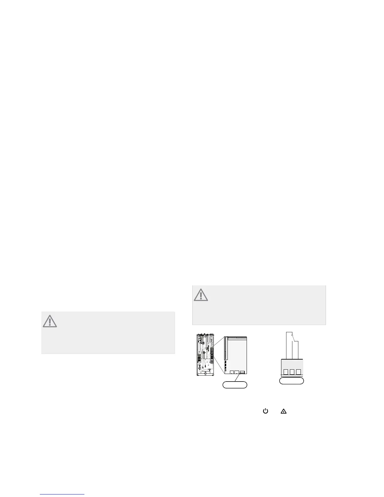
$$;
&121&
APH
VVM 500
AA3-X7
The picture shows the relay in the alarm position.
When switch (SF1) is in the "
"or“ ” position the
relay is in the alarm position.
External circulation pump or hot water circulation
pump connected to the buzzer alarm relay as illustrated
below.
27Chapter 5 | Electrical connectionsNIBE™ VVM 310