H
Heather MartinezJul 31, 2025
How to troubleshoot a Nice Gate Opener that won't power on?
- SsamantharussoJul 31, 2025
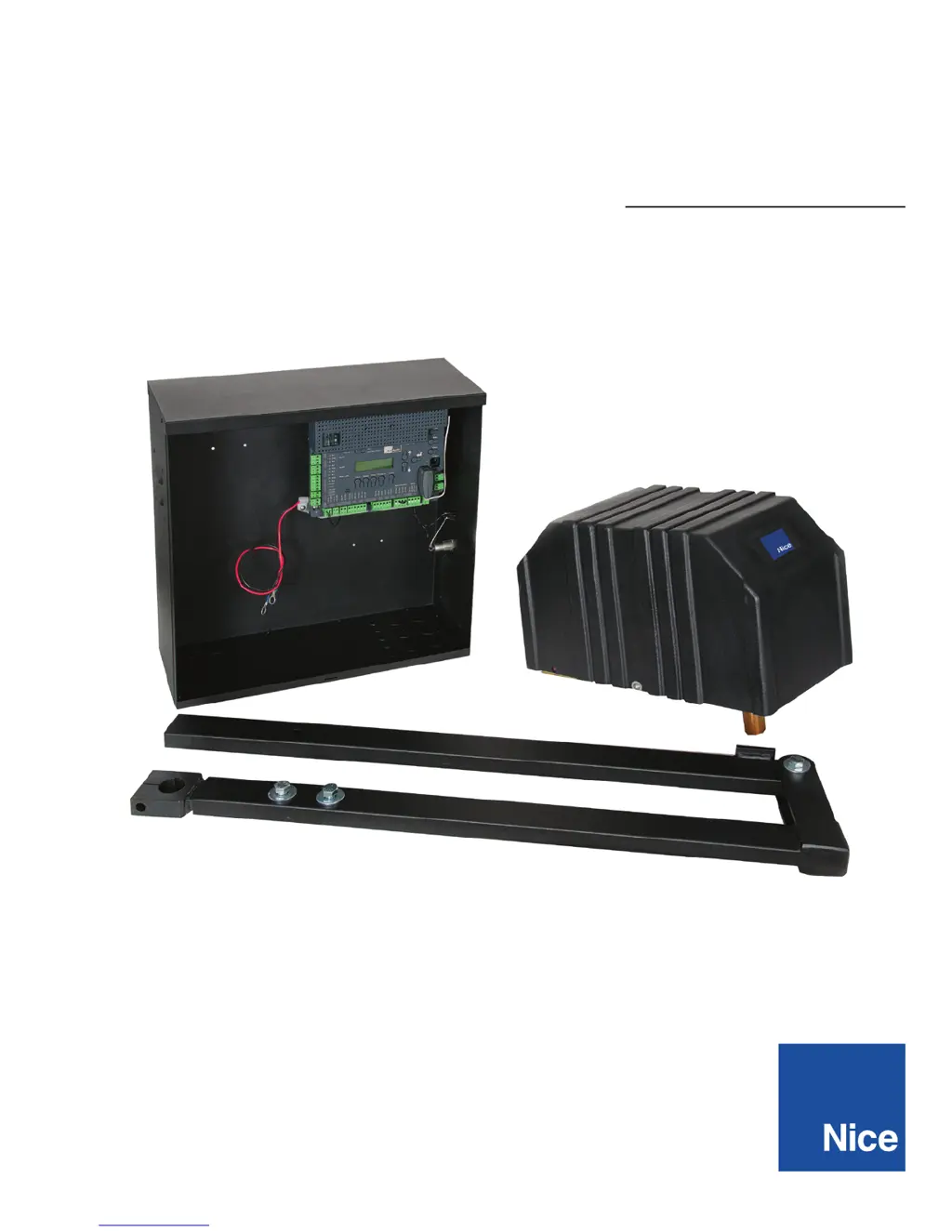
If the Nice Gate Opener operator will not power on and the power LED is off, make sure the power to the circuit board is turned on. Check the terminal block wiring for loose or broken wires. If the voltage measures OK, check the terminal block. Also, check the fuses, including both AC and DC fuses, in the installation.