23 - GENERAL LAYOUT AND SAFETY ACCESS
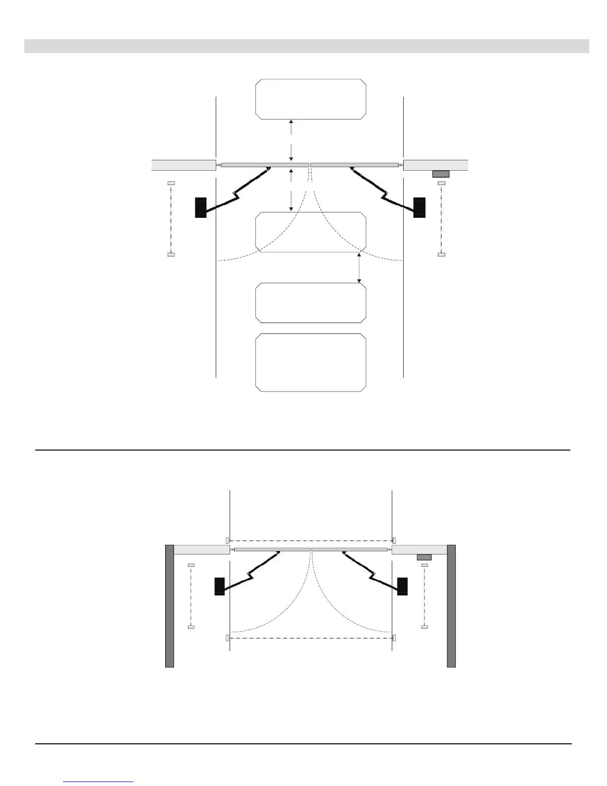
Entrapment Protection Inputs - Typical Installation Diagram Utilizing Loop Sensors and Photocells
Figure - LAYOUT FOR IN-GROUND LOOPS
Figure - LAYOUT FOR PHOTOCELLS
Open
Direction
Eye
Open
Direction
Eye
Outside
Gate
Close Direction Eye
Possible Entrapment Zones - Typical Installation Diagram Utilizing Photocells
(Installer must assess site for any other entrapment risks)
Close Direction Eye
Open
Direction
Eye
Open
Direction
Eye
(Possible Entrapment Zone