25
21 - OPTIONAL INPUTS
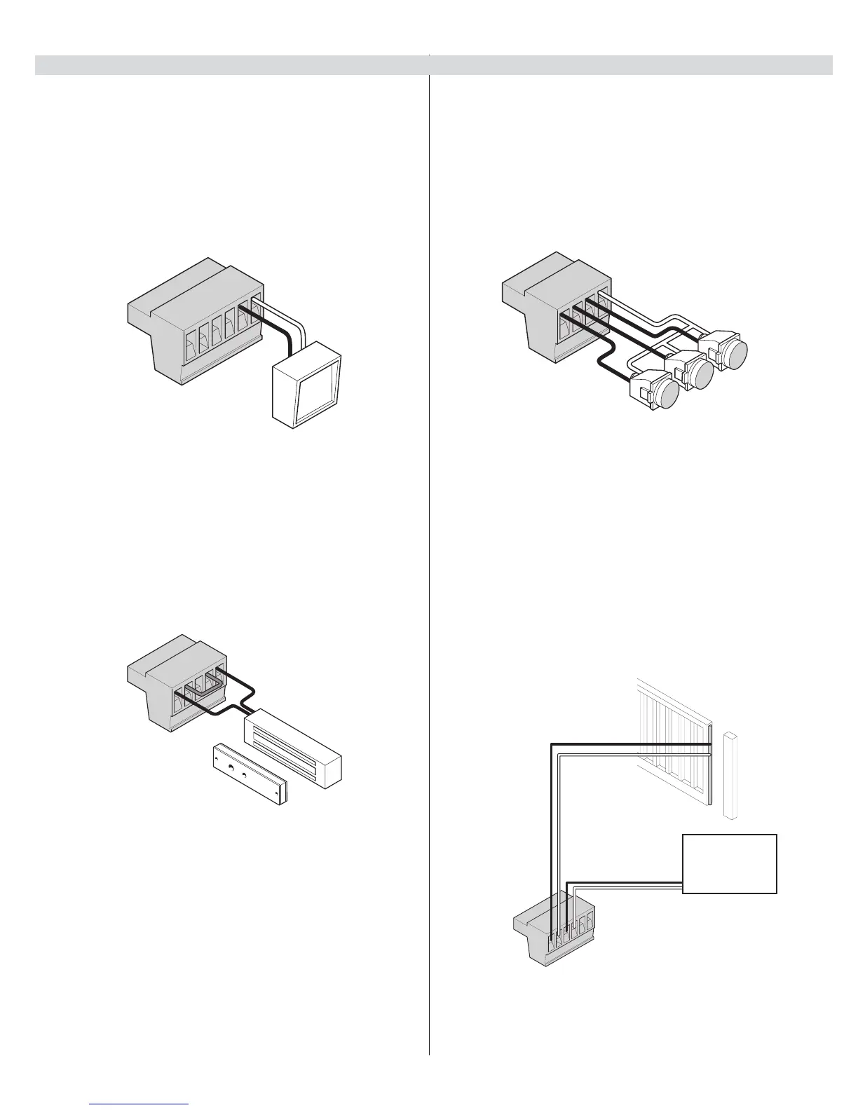
21.1 - Fire dept. connection
32 FIRE
33 GND
Dry contact input for a re department control switch. Normally Open (NO)
contact must be shorted to ground through a switch to open the gate. The
FAIL SAFE connector which is shorted at the factory with a jumper (Normally
Closed NC), may be wired in parallel with the Fire input to release the motor
in the event of an emergency entry by the re department during a power
failure.
Figure - GUARD STATION INPUTS
21.4 - Exit and edge inputs wiring diagram
28 EDGE
29 GND
30 EXIT
31 GND
The EDGE input may be congured as a monitored ANALOG input, or DIGITAL
(NC or NO) input. The EDGE sensor input is intended for ANSI/UL 325 listed gate
edge sensors to protect against entrapment and hazardous pinch points along
the moving edge of the closing gate. The EXIT sensor input is provided to activate
to open the gate, or re-open a closing gate, upon sensing an exiting vehicle.
Figure - FIRE DEPT. INPUT
21.2 - Magnetic lock connection
7 NC
8 Com (Common)
9 NO
10 GND
11 V+ (Voltage is determined by incoming power supply)
This connection is used to install the magnetic lock. In this instance a gate
can be locked magnetically to prevent a forced opening. Consult lock manual
for specics on installation and wiring
Figure - EXIT AND EDGE INPUTS
Figure - MAGNETIC LOCK WIRING
(EXAMPLE)
28
29
30
31
32
33
FIRE
DEPT.
34
35
36
37
CLOSE
STOP
OPEN
NO
NC
NO
28
29
30
31
32
33
Exit Device
21.3 - Guard station
34 OPEN
35 STOP
36 CLOSE
37 GND
With the Guard Station switches installed, the user can operate the gate by
pushing the respective buttons for the command that is desired. Gate Open
and Close are controlled by NORMALLY OPEN (NO) and Stop is controlled by
NORMALLY CLOSED (NC) momentary switches.
NOTE: If the guard station inputs are not used
STOP (35) and GND (37) need to
be tied together