19
3501 WIRING (RIGHT HINGED GATE)3501 WIRING (LEFT HINGED GATE)
Limit switch wiring
Connect the 3501 cable to the 5-pin connector as shown below.
Motor wiring
Connect the motor leads to the 3-pin connector as shown
below.
Note: If the gate moves in the opposite direction from what
is expected, reverse the motor wiring from what is shown.
(Black to Pin 1, Red to Pin 3).
Single and Dual wiring
Install the 5 and 3-pin connector into the connection labeled
“Motor 1” on the controller as shown. For a dual gate installation
install the 5 and 3-pin connector for the left hinge gate operator
into the connection labeld, “Motor 1” and connector for right
hinge gate operator labeled, “Motor 2”.
Note: (Motor 1) - Make sure motor lead connector is plugged in
below the limit 5 pin terminal connector
Limit switch wiring
Connect the 3501 cable to the 5-pin connector as shown below.
Motor wiring
Connect the motor leads to the 3-pin connector as shown
below.
Note: If the gate moves in the opposite direction from what is
expected, reverse the motor wiring from what is shown. (Red
to Pin 1, Black to Pin 3).
Single and Dual wiring
Install the 5 and 3-pin connector into the connection labeled
“Motor 1” on the controller as shown. For a dual gate installation
install the 5 and 3-pin connector for the left hinge gate operator
into the connection labeld, “Motor 1” and connector for right
hinge gate operator labeled, “Motor 2”.
Note: (Motor 1) - Make sure motor lead connector is plugged in
below the limit 5 pin terminal connector
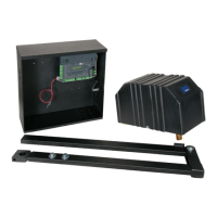
15.3 - Limit and motor wiring (Single and Dual Gate Application)
15 - WIRING (CONT.)
WHITE
ORANGE
GREEN
DO NOT USE
BLACK
RED
MOTOR 1
3501 - LEFT HINGED GATE
WHITE: Close Limit
ORANGE: Open Limit
GREEN: Limit Common
3501 ACTUATOR
3501 ACTUATOR
MOTOR LEADS
NOTE: If gate moves in opposite
direction from what is expected,
reverse the motor power lead
wiring.
WHITE: Close Limit
ORANGE: Open Limit
GREEN: Limit Common
MOTOR 1 MOTOR 2
WHITE
GREEN
ORANGE
ORANGE
GREEN
WHITE
DO NOT USE