1 - Overview 4
2 - General Safety Information 5
3 - Use of Vehicle Detectors 8
4 - Gate Construction and Safety 8
5 - Maintenance of Gate Systems 10
6 - Entrapment Protection 11
7 - Compatible External Sensors 12
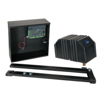
8 - PARTS IDENTIFICATION 13
9 - POST INSTALLATION 13
9.1 - Post location guide 13
9.2 - Post height 14
9.3 - Welding mounting bracket 14
10 - CHASSIS MOUNTING 15
11 - CONTROL ARM ASSEMBLY 15
12 - GATE BRACKET MOUNTING 16
13 - CONTROL BOX MOUNTING 17
14 - CIRCUIT BOARD LAYOUT 17
15 - WIRING 18
15.1 - Incoming power wiring 18
15.2 - Chassis wiring 18
15.3 - Limit and motor wiring 19
16 - SETTING THE LIMIT SWITCHES 20
17 - LEARNING MODE 21
18 - ACCESSORY INPUTS AND OUTPUTS 22
19 - 120VAC POWER WIRING 24
20 - SOLAR PANEL CHART 24
21 - OPTIONAL INPUTS 25
21.1 - Fire dept. connection 25
21.2 - Magnetic lock connection 25
21.3 - Guard station 25
21.4 - Exit and edge inputs wiring diagram 25
21.5 - Radio receiver connection (third party) 26
21.6 - Optional power output 26
22 - INSPECTION AND OPERATION 26
23 - GENERAL LAYOUT AND SAFETY ACCESS 27
24 - ACCESSORIES AND SENSORS 28
25 - IRB-RET WIRING DIAGRAM 29
26 - GEM-103 WIRING DIAGRAM 29
27 - WEL-200 WIRING DIAGRAM 30
28 - MAINTENANCE SCHEDULE 31
29 - TROUBLESHOOTING 31
30 - OPERATOR DIMENSIONS 33
30.1 - Control Box General Dimensions 33
30.2 - 3501 General Overview 34
31 - EXPLODED VIEWS 35
31.1 - Control box 35
31.2 - Motor Chassis 36
31.3 - Arm Assembly 37
32 - WARRANTY 38
33 - INSTALLATION CHECKLIST 39
34 - Appendix - French Translations 40-43
TABLE OF CONTENTS